Current Limiter
Behavioral model of current limiter

Libraries:
Simscape /
Electrical /
Semiconductors & Converters
Description
The Current Limiter block provides a behavioral model of a current limiter. Use this block to model current limiting in power supplies and motor drives or in components that limit inrush current.
The block limits the current using a hyperbolic tangent function,
where:
i is the current through the component.
v is the voltage drop across the component.
iLIM is the current limit.
vLIM is the approximate voltage drop across the component when the current limit is active.
gLIM is the rate of change of current with respect to the voltage drop at large current magnitudes. This variable is also called the limit-state conductance.
The gLIMv term represents how you cannot limit the current to a fixed value for arbitrarily high voltages. This term also improves numerical properties during simulation.
Choose a value for gLIM such that gLIMv is small compared to iLIM when v is equal to the maximum voltage drop that you expect.
This figure shows a typical i-v characteristic for the Current Limiter block. When i is lower than iLIM, the device behaves like a resistor. The conductance is approximately equal to 4vLIM/vLIM. As i approaches iLIM, the rate of change of current with voltage falls rapidly to the limit-state conductance gLIM.
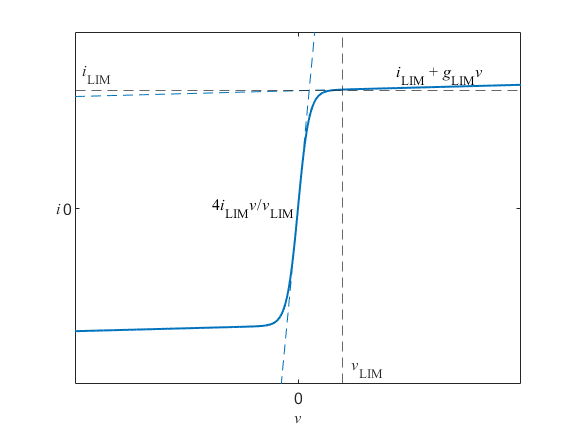
To choose a suitable value for vLIM, compare your i-v characteristic to a plot from a datasheet. Smaller values give you a steeper gradient at low currents, but the solver needs tight tolerances and smaller step sizes.
When v = vLIM,
The current through the component is therefore approximately equal to the current limit.
The Current Limiter block limits positive and negative currents. To limit the current to iLIM in one direction only, connect the Current Limiter block to a Diode block. To prevent any current limiting in the reverse-biased direction, connect the two blocks in series. To block any current in the reverse-biased direction, connect the two blocks in parallel.
To use the same current limit iLIM for
positive and negative currents, set the Limiter type parameter to
Constant symmetric limits. The Current
limit parameter defines the magnitude of the current limit.
To use a different current limit for positive and negative currents, set the
Limiter type parameter to Constant asymmetric
limits. The Current limit parameter defines the
current limit for positive currents and the Reverse direction current
limit parameter defines the limit for negative currents.
To use a current limit that is a function of time, set the Limiter
type parameter to Variable limit. The input
physical signal to the Lim port defines the magnitude of the
current limit.
Thermal Port
This block has one optional thermal port. To control the visibility of the thermal port, set the Modeling option parameter to either:
No thermal port— The block does not contain a thermal port.Show thermal port— The block contains one thermal conserving port.
The thermal port model contains a thermal mass. The power dissipated by the current limiter, plus the heat flow into the thermal port, drives the thermal mass differential equation,
where:
m is the thermal mass.
T is the thermal port temperature.
Ploss is the electrical loss, v·i.
QH is the heat flow from the external network into the thermal port.
Variables
To set the priority and initial target values for the block variables before simulation, use the Initial Targets section in the block dialog box or Property Inspector. For more information, see Set Priority and Initial Target for Block Variables.
Nominal values provide a way to specify the expected magnitude of a variable in a model. Using system scaling based on nominal values increases the simulation robustness. You can specify nominal values using different sources, including the Nominal Values section in the block dialog box or Property Inspector. For more information, see System Scaling by Nominal Values.
Examples
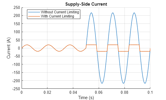
Protect Components During Fault Using Current Limiter Block
Use a Current Limiter block to protect a resistor from a short circuit or failure of the load.
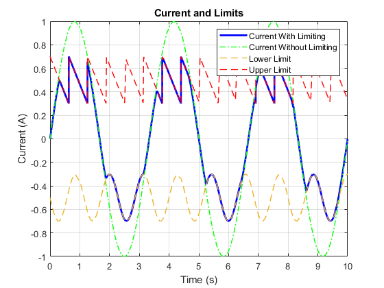
Configure Current Limiter with Variable Asymmetric Limits
Implement a current limiter device with variable asymmetric limits using the Current Limiter block in Simscape™ Electrical™.