Main Content

Ideal Switch

Implement ideal switch device

  • Ideal Switch block

Libraries:
Simscape / Electrical / Specialized Power Systems / Power Electronics

Description

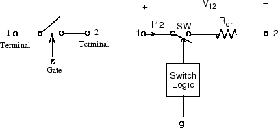
The Ideal Switch block does not correspond to a particular physical device. When used with appropriate switching logic, it can be used to model simplified semiconductor devices such as a GTO or a MOSFET, or even a power circuit breaker with current chopping. The switch is simulated as a resistor Ron in series with a switch controlled by a logical gate signal g.

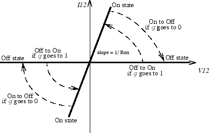
The Ideal Switch block is fully controlled by the gate signal (g > 0 or g = 0). It has the following characteristics:

  • Blocks any forward or reverse applied voltage with 0 current flow when g = 0

  • Conducts any bidirectional current with quasi-zero voltage drop when g > 0

  • Switches instantaneously between on and off states when triggered

The Ideal Switch block turns on when a positive signal is present at the gate input (g > 0). It turns off when the gate signal equals 0 (g = 0).

The Ideal Switch block also contains a series Rs-Cs snubber circuit that can be connected in parallel with the ideal switch (between nodes 1 and 2).

Examples

The power_switch example uses the Ideal Switch block to switch an RLC circuit on an AC source (60 Hz). The switch, which is initially closed, is first opened at t = 50 ms (3 cycles) and then reclosed at t = 138 ms (8.25 cycles). The Ideal Switch block has 0.01 ohms resistance and no snubber is used.

Assumptions and Limitations

The Ideal Switch block is modeled as a current source. It cannot be connected in series with an inductor, a current source, or an open circuit, unless its snubber circuit is in use.

Ports

Input

expand all

Simulink signal to control the opening and closing of the switch.

Output

expand all

The Simulink output of the block is a vector containing two signals. You can demultiplex these signals by using the Bus Selector block provided in the Simulink library;

Signal

Definition

Units

1

Ideal switch current

A

2

Ideal switch voltage

V

Conserving

expand all

Specialized electrical conserving port associated with the terminal 1 of the ideal switch.

Specialized electrical conserving port associated with the terminal 2 of the ideal switch.

Parameters

expand all

To edit block parameters interactively, use the Property Inspector. From the Simulink Toolstrip, on the Simulation tab, in the Prepare gallery, select Property Inspector.

Internal resistance of the switch device, in ohms (Ω). The Internal resistance Ron parameter cannot be set to 0.

Initial state of the Ideal Switch block. The initial status of the Ideal Switch block is taken into account in the steady-state calculation.

Snubber resistance, in ohms (Ω). Default is 1e5. Set the Snubber resistance Rs parameter to inf to eliminate the snubber from the model.

Snubber capacitance in farads (F). Default is inf. Set the Snubber capacitance Cs parameter to 0 to eliminate the snubber, or to inf to get a resistive snubber.

If selected, add a Simulink output to the block returning the ideal switch current and voltage.

References

[1] Mohan, N., T.M. Undeland, and W.P. Robbins, Power Electronics: Converters, Applications, and Design, John Wiley & Sons, Inc., New York, 1995.

Extended Capabilities

C/C++ Code Generation
Generate C and C++ code using Simulink® Coder™.

Version History

Introduced before R2006a

See Also