Hardware Mapping Peripherals for Texas Instruments® C2000 Processors
Select the configurations for the peripherals in the model deployed to the hardware board
Since R2022b
Description
The peripheral configurations for devices listed in the Hardware Mapping tool for Texas Instruments C2000 processors appear in the selected block in the Browser > Peripherals. This table shows the association between the driver block, simulation interface block, and Hardware Mapping tool hardware configuration.
| Driver Block | Interface Block | Hardware Configuration |
|---|---|---|
| ADC Read (SoC Blockset) | ADC Interface (SoC Blockset) | ADC |
| PWM Write (SoC Blockset) | PWM Interface (SoC Blockset) | PWM |
Properties
ADC
Select the ADC module A through
D on the hardware board.
Identify the start-of-conversion trigger by number.
Select the resolution of the digital conversion output.
Select the input channel to which this ADC conversion applies.
Define the length of the acquisition period in ADC clock cycles. The value of this
parameter depends on the SYSCLK and the minimum ADC sample
time.
Select the event source that triggers the start of the conversion.
At the end of conversion, use the ADCINT1 or
ADCINT2 interrupt to trigger a start of conversion. This
loop creates a continuous sequence of conversions. The default selection,
No ADCINT disables this parameter. To set the interrupt,
select the Post interrupt at EOC trigger option, and choose
the appropriate interrupt.
Enable post interrupts when the ADC triggers EOC pulses. When you select this option, the dialog box displays the Interrupt selection and Interrupt continuous mode options.
Select which ADCINT interrupt the ADC
posts to after triggering an EOC pulse.#
When the ADC generates an end of conversion (EOC) signal, generate an
ADCINT interrupt, whether the
previous interrupt flag has been acknowledged or not.#
PWM
Select the appropriate ePWM module,
ePWMx, where x is a
positive integer.
Set the high speed time base clock prescaler divider,
HSPCLKDIV.
Use the Time base clock, TBCLK, prescaler divider,
CLKDIV, and the high speed time base clock,
HSPCLKDIV, prescaler divider, HSPCLKDIV, to
configure the Time-base clock speed, TBCLK, for the
ePWM module. Calculate TBCLK using this
equation: TBCLK = PWM clock/(HSPCLKDIV * CLKDIV).
For example, the default values of both CLKDIV and
HSPCLKDIV are 1, and the default frequency of PWM clock is 200 MHz,
so: TBCLK in Hz = 200 MHz/(1 * 1) = 200 MHz TBCLK
in seconds = 1/TBCLK in Hz = 1/200 MHz = 0.005 μs.
Set the period of the ePWM counter waveform.
The timer period is in clock cycles:
| Count Mode | Calculation | Example |
|---|---|---|
Up or down | The value entered in clock cycles is used to calculate time-base period,
TBPRD, for the ePWM timer register. The
period of the ePWM timer is TCTR = (TBPRD + 1) *
TBCLK, where TCTR is the timer period in seconds,
and TBCLK is the time-base clock. | For |
Up-down | The value entered in clock cycles is used to calculate the time-base
period, TBPRD, for the ePWM timer
register. The period of the ePWM timer is TCTR = 2 *
TBPRD * TBCLK, where TCTR is the timer period in
seconds and TBCLK is the time-base clock. | For EPWMCLK frequency = 200 MHz and
TBCLK = 5 ns. When the timer period is entered in clock
cycles, TBPRD = 10000, and the ePWM timer
period is calculated as TCTR = 100 µs. For the default action
settings on the ePWMx tab, the
ePWM period = 100 µs. |
The initial duty cycle of the waveform from the time the PWM peripheral starts operation until the ePWM input port receives a new value for the duty cycle is Timer period / 2.
Set the initial count value of the comparator in clock cycles.
Enables to provide a timer phase offset value.
The specified offset value is loaded in the time base counter on a synchronization
event. Enter the phase offset value, TBPHS, in
TBCLK cycles from 0 to 65535.
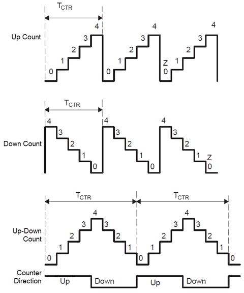
Specify the counting mode of the PWM internal counter. This figure shows three counting waveforms.
This group determines the behavior of the action qualifier (AQ) submodule. The AQ
module determines which events are converted into one of the various action types,
producing the required switched waveforms of the ePWMA circuit. The
ePWMB always generates a complement signal of
ePWMA.
This group determines the behavior of the Action Qualifier (AQ) submodule. The AQ
module determines which events are converted into one of the various action types,
producing the required switched waveforms of the ePWMA circuit. The
ePWMB always generates a complement signal of
ePWMA.
This group determines the behavior of the action qualifier (AQ) submodule. The AQ
module determines which events are converted into one of the various action types,
producing the required switched waveforms of the ePWMA circuit. The
ePWMB always generates a complement signal of
ePWMA.
When shadow mode is not enabled, the CMPA register refreshes
immediately. Provide different reload mode for CMPA register.
The time when the counter period resets based on the following condition:
Counter equals to zero (CTR=Zero)– Refreshes the counter period when the value of the counter is 0.Counter equals to period (CTR=PRD)– Refreshes the counter period when the value of the counter is period.Counter equals to Zero or period (CTR=Zero or CTR=PRD)– Refreshes the counter period when the value of the counter is 0 or period.Freeze– Refreshes the counter period when the value of the counter is freeze.
This parameter specifies the counter match condition that triggers an ADC start of the conversion event. The choices are:
Counter equals to zero (CTR=Zero)– Triggers an ADC start of the conversion event when theePWMcounter reaches 0.Counter equals to period (CTR=PRD)– Triggers an ADC start of the conversion event when theePWMcounter reaches the period value.Counter equals to Zero or period (CTR=Zero or CTR=PRD)– Triggers an ADC start of the conversion event when the time base counter,TBCTR, reaches zero or when the time base counter reaches the period,TBCTR=TBPRD.Disable– Disable ADC start of conversion event.Counter is– Triggers an ADC start of the conversion event when the counter equals the specified comparator and the counterdirectionand equal to CMPxdirectionis eitherincrementingordecrementing.
This parameter registers that an interrupt occurs for the specified event and generates interrupt service routine (ISR) code to be used by the Task Manager. The choices are:
Counter equals to zero (CTR=Zero)– Generates an ISR for when theePWMcounter reaches 0.Counter equals to period (CTR=PRD)– Generates an ISR for when theePWMcounter reaches the period value.Counter equals to Zero or period (CTR=Zero or CTR=PRD)– Generates an ISR for when the time base counter,TBCTR, reaches zero or when the time base counter reaches the period,TBCTR=TBPRD.Disable– Disable ISR generation.Counter is– Generates an ISR for when the counter equals the specified comparator and the counterdirectionand equal to CMPxdirectionis eitherincrementingordecrementing.
This parameter specifies the deadband delay for rising edge and falling edge in time-base clock cycles.
Version History
Introduced in R2022b