Test Integrated Code
Test Integrated C Code
If you have a model that integrates C code with a C Caller block, you can test the C code with the Test Manager and a test harness.
The C Caller block uses configuration parameters to define the custom code. If you change the configuration parameters, synchronize the parameters between the test harness and the model. For more information, see Synchronize Changes Between Test Harness and Model and Create or Import Test Harnesses and Select Properties.
If you change the test harness configuration parameters, you can push the configuration set to the main model. Click Push Changes, or use
sltest.harness.push.If you change the main model configuration parameters in the main model, and you want to update the test harness parameters, the test harness must copy the configuration parameters on rebuild. You can set this property in two ways:
When you create the test harness, select Update Configuration Parameters and Model Workspace data on rebuild. You can also select Rebuild Harness on Open, which rebuilds every time the harness opens.
For existing test harnesses, in the harness preview, select one or more of Rebuild Harness > Rebuild on Open, , or Rebuild Harness without Compiling Model, and Update Harness Configuration Settings and Model Workspace. The Update Harness Configuration Settings and Model Workspace option updates the settings every time a rebuild occurs.
Testing Code in an S-Function Block
This example shows how to use a test harness to test code in an S-Function block. The main model for this example is a controller-plant model of an air conditioning/heat pump unit.
Note that his example works only on a 64–bit Windows® platform.
S-Functions are computer language descriptions of Simulink® blocks written in MATLAB®, C, C++ or Fortran®. You can test code wrapped in S-Functions by using test harnesses. Testing code in S-Functions can be helpful for regression testing of legacy code and for testing your code in a system context.
Open the Model
sltestHeatpumpSfunExample
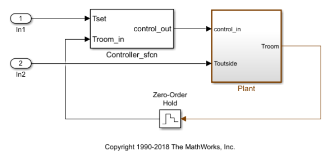
In the example model:
The controller is an S-Function that accepts room temperature and specified temperature inputs.
The controller output is a bus with signals that control the fan, heat pump, and the direction of the heat pump (heat or cool).
The plant accepts the control bus. The heat pump and the fan signals are Boolean, and the heat pump direction is specified by +1 for cooling and -1 for heating.
Temperature Condition States
The test covers four temperature conditions. Each condition corresponds to one operating state with fan, pump, and pump direction signal outputs.

Create Test Case
1. On the Apps tab, under Model Verification, Validation, and Test, click Simulink Test. Then, on the Tests tab, click Simulink Test Manager.
2. From the Test Manager toolstrip, click New > Test File to create a test file. Name and save the test file.
3. In the test case, under System Under Test, click the ![]() button to load the current model into the test case.
button to load the current model into the test case.
Create Test Harness
1. In the model, right-click the Controller_sfcn subsystem and select Test Harness > Create for ‘Controller_sfcn’.
2. Set the harness properties. In the Basic Properties tab, set the test harness properties. Set Name to test_harness_1 and Set Sources and Sinks to None and Scope.
3. Click OK to create the test harness.
4. In the Test Manager highlight New Test Case 1. In System Under Test, expand Test Harness. Refresh the test harness list and select test_harness_1 for the Harness.
Add Inputs and Set Simulation Parameters
Create inputs in the test harness, with a constant Tset and a time-varying Troom_in.
1. In the test harness model, connect a Constant block to the Tset input and set the value to 75.
2. Add a Sine Wave block to the harness model to simulate a temperature signal. Connect the Sine Wave block to the conversion subsystem input Troom_in.
3. Double-click the Sine Wave block and set the parameters:

Select Interpret vector parameters as 1–D. Then, click OK.
The resulting harness is:

4. In the Simulation toolstrip, set the Stop Time to 3600.
Obtain Baseline Data
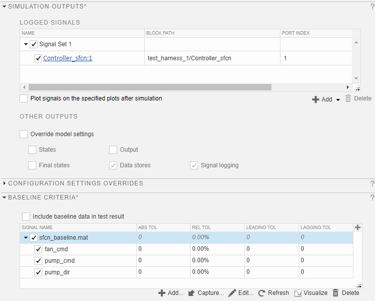
1. In the Test Manager test case, in Simulation Outputs, click Add. Highlight the output bus from the controller S-Function.

2. In the Connect popup, select Controller_sfcn:1(all) and click Click to update diagram. Then, return to the Test Manager and click Done in the dialog box.
3. Under Baseline Criteria, click Capture to record a baseline data set from simulating the test harness. In the Capture Baseline dialog box, enter sfcn_baseline as the MAT format File name and click Capture. The baseline signals appear in the table.
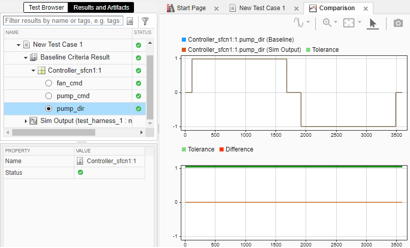
Run Test Case and View Results
1. Run the test case. The test results appear in the Results and Artifacts pane.
2. Expand the results to view the baseline criteria result. The baseline test passes because the simulation output is identical to the baseline data.