Create External Data Files to Use in Test Cases
You can create Microsoft® Excel® files, MAT files and MATLAB® scripts for test case data, such as inputs, baseline data, and parameter overrides. The files use specific formats and can contain multiple types of data.
Note
You can create files for input data only for tests that run in the current release. To select the current release in the Test Manager, in the System Under Test section of a test case, use Select releases for simulation.
Generate an Excel File
This example shows how to generate an Excel® file for a system under test (SUT). The generated spreadsheet extracts data from the model or test harness. If needed, you can edit the spreadsheet to add other data. Then, you can import the data from the file into Simulink® Test™ as a test case.
To extract data from the model, use the Create Test from Spreadsheet wizard. The wizard parses the SUT for test attributes and generates a template spreadsheet and a test case with these types of data:
Inputs — Inputs are characterized by root input ports
Parameters — Named parameters in the model
Comparison signals — Logged signals and output ports
The wizard allows you to filter and edit the attributes needed for testing. The resulting spreadsheet has separate column sets for inputs, parameters, and comparison signals. If your test requires multiple iterations, the wizard creates a separate sheet in the same file for each iteration. You can expand the spreadsheet to add time-based signal data, tolerances, and parameter overrides.
Open the Model and the Test Manager
open_system("coordinate_transform_test")
sltest.testmanager.view
Open and Use the Create Test from Spreadsheet Wizard
In the Test Manager, select New > Test from Spreadsheet..
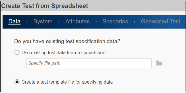
Data Page
Select Create a test template file for specifying data and click Next.
System Page
Leave coordinate_transform_test as the Model and None as the Harness. Click Next.

Attributes Page
Select the test attribute categories to include in the spreadsheet. For this example, leave Inputs and Parameters and Yes, include all attributes in the spreadsheet selected. Click Next.

Note that if you change the SUT during the selection process, click Refresh to synchronize the attribute lists with the SUT.
Also, note that if you do not want to use all the attributes in a category as is, select No, I want to filter and edit the attributes. Then when you click Next, the Inputs and Parameters tabs are displayed. Select the inputs to use and clear the parameters that are not needed. A Comparison tab is also displayed if you selected Comparisons in addition to the Inputs and Parameters on the Attributes page. In the Comparison tab, select the signals to use for the baseline comparisons and if desired, set the tolerances. To specify different tolerances for each signal, open and edit the spreadsheet after the wizard generates the spreadsheet
Scenarios page
On the Scenarios page, enter 1 as the number of test scenarios and leave the base name for the sheets in the spreadsheet as Scenario. Click Next.
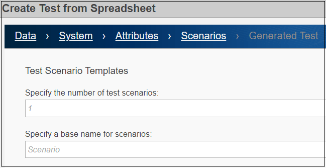
Note that if you enter a number greater than 1, the wizard generates each scenario as a separate sheet in the spreadsheet. The Test Manager uses each sheet as a separate iteration.
Generated Test page
On the Generated Test page, specify coordinate_test.mldatx as the test file name and the coordinate_test.xlsx as the Excel spreadsheet name. Click Done to create the test and generate the test and Excel files in the working directory.
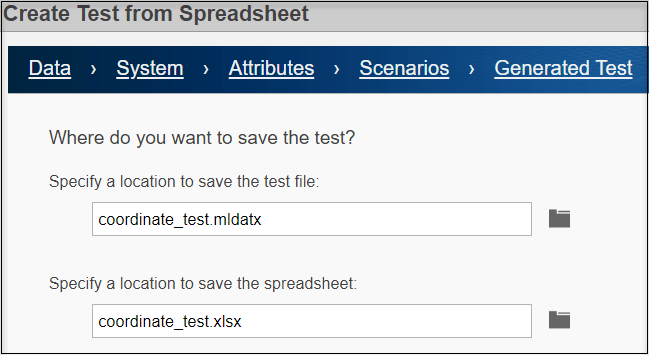
The wizard creates the two files:
Excel spreadsheet — The spreadsheet includes columns for inputs, parameters, and comparison signals. Inputs and comparisons have different time bases. The wizard generates an identical sheet for each test scenario. Complete the spreadsheet with specific values, such as parameter overrides, to uniquely define each scenario. To view the Excel file, open
coordinate_test.xlsx. For more information on the file format, see Microsoft Excel Import, Export, and Logging Format.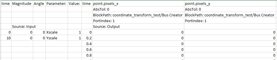
Test file — The test case imports the Excel spreadsheet and creates the test case. The resulting test case in the Test Manager has the Create Test Case from External File option selected. The Parameter Overrides and Inputs sections include data from the file.

The fields in the spreadsheet are locked in the Test Manager. To change the locked fields, edit the spreadsheet outside of the Test Manager and MATLAB. If you change one or more parameters and selected Comparison on the Attributes page, capture the baseline again by clicking Capture in the Baseline Criteria section.
Input, Baseline, and Parameter Override Test Case Data Formats in Excel
As an alternative or in addition to using the wizard, you can specify signal data and time data associated with the signal in a Microsoft Excel file to use as input to your test case or as baseline criteria. To support a range of models and configurations, you can specify signal data of most data types. You can indicate whether signals are scalar, multidimensional, or complex. You can optionally specify the data type, block path and port index, units, interpolation type, and function-call execution times. You can also specify values for parameter overrides. If your Excel file has more than one sheet, the data on each sheet is used in the Test Manager as a separate iteration.
For general information on how to format data in Excel files, see Microsoft Excel Import, Export, and Logging Format. For information on how to use Excel and other external files, see Use External File Data in Test Cases.
Excel File Inputs Format
To create an Excel file and view the format for model input data, click
Create in the Inputs section of a test
case in the Test Manager. Then, set Excel as the File
format. The input data includes a time column and a column of data
values for each model inport. See the example spreadsheet in Multiple Runs.
You can add a table iteration to the test case and assign the input file to it by clicking Create in the Inputs section of the Test Manager. Then, in the Create Input Data File dialog box, click Add iterations to run this input. After you create the input file, continue to specify the iteration. For more information on iterations, see Test Iterations.
To use an existing Excel file for the model input data, click Add.
Excel File Baseline Data Format
To view the Excel format for the baseline data, first capture the baseline from
your model. Click Capture in the Baseline
Criteria section of a test case in the Test Manager. Then, select
Excel as the File format. The Excel file
includes the time and associated value for each signal in the model that is marked
for logging. Information about the logged signal includes the signal name, absolute
tolerance, path of the block from which the signal originates, the port index of the
block, and the source type.
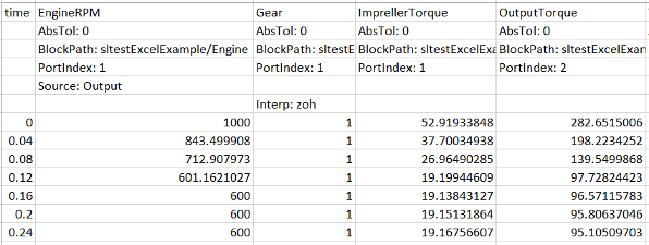
This sample baseline spreadsheet includes uniquely named signals and signal block paths. Causes of signals not being well defined are:
When a signal does not have a name in the model, a name is automatically assigned to it in the spreadsheet.
When you manually create a spreadsheet and do not include the signal name, a signal name with the format
block_name:
                                port_index
is assigned to the signal.When the signal name included in a spreadsheet does not uniquely identify the signal, add the block path for that signal. For example, signals with the same names at different levels in the model hierarchy are not uniquely identified if you only specify the name. If you do not include the block path, the first signal with that name is used.
You can include both baseline (Source:Output) data and input
(Source:Input) data in the same Excel file. See the example
spreadsheet in Multiple Runs.
To use a manually created Excel file as expected outputs, click Add in the Baseline Criteria section of the test case in the Test Manager and specify the file name.
To edit external files from the Baseline Criteria section of the Test Manager, select the file and click Edit. Excel files open in Excel by default, but you can also open and edit an Excel file outside of MATLAB.
Excel File Parameter Overrides Format
The parameters in a spreadsheet are in two columns labeled Parameter, which is the parameter name, and Value, which is the parameter value. See the example spreadsheet in Multiple Runs. To override a parameter, change its value in the spreadsheet before you add the file to the test case.
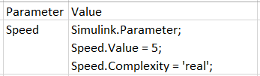
For parameter types such as Simulink.Parameter,
Simulink.DataDictionary, or
Simulink.LookupTable objects, you can specify only the values
to override. The values you do not specify use the values set in the model. The
Excel format for overriding these parameters is:
To use parameter overrides from an Excel file, click Add > Add File in the Parameter Overrides section of a test case in the Test Manager.
Create a MAT File for Test Case Inputs
You cannot manually create a MAT file to use in a test case. Follow these steps to generate a MAT file.
In the test case, under System Under Test, specify the model whose input data you want to create a MAT file for.
In the Inputs section of the test case, click Create.
In the dialog box, set File Format to
MAT. Specify the location for the MAT file and click Create. To edit an existing file, select the file and click Edit. The Signal Editor opens.In the left pane of the Signal Editor, expand the data node. Then select the signal whose data you want to add.
Specify the signal data. In the bottom pane, select the data type from the list, and enter the time and signal data for the signal.

To update your signal data, click Apply.
After adding the signal data, click Save.
MATLAB Script Format for Test Case Data
You can use MATLAB scripts to specify test case data. The files include MATLAB language commands formatted in the same way as code you write at the command line. To edit a script file, open the file in a text editor. For example, a MATLAB script file that sets two parameter values contains this code:
a_min = 1.3;
a_max = 22.4;
See Also
sltest.testmanager.BaselineCriteria | sltest.testmanager.TestInput