Create a Test Harness
A test harness is a model that isolates the component under test, with inputs, outputs, and verification blocks configured for testing scenarios. You can create a test harness for a model component or for a full model. A test harness gives you a separate testing environment for a model or a model component. For example:
You can unit-test a subsystem by isolating it from the rest of the model.
You can create a closed-loop testing scenario for a controller by adding a plant model to the test harness.
You can keep your main model clear of unneeded verification blocks by placing Model Verification and Test Assessment blocks in the test harness.
To assign a test harness to a test case, select Test Harness in the System Under Test section of the Test Manager.
You can save the harness with your model, or you can save it in an external file. If your model is under change management, consider saving the test harness in an external file. The harness works the same whether it is internal or external to the model. For more information, see Manage Test Harnesses and Synchronize Changes Between Test Harness and Model.
Create the Harness
In this example, you create a harness directly from a model. The harness tests the
shift_logic subsystem of the sltestCarRootInport
model.
Open the model
sltestCarRootInport.openExample("sltestCarRootInport.slx")Right-click the
shift_logicsubsystem. To add the Simulink Test app options to the menu, point to Select Apps and click the Simulink Test button . Then, in the Simulink Test app section, click the Add
Test Harness for Subsystem button
. Then, in the Simulink Test app section, click the Add
Test Harness for Subsystem button  .
.In the Create Test Harness dialog box, specify the inputs, outputs, and other options:
Use Constant blocks to provide input signals. Under Sources and Sinks, set the source to
Constantand the sink toScope.Leave the other options with their default selections. By default:
The harness saves with the model file.
The harness synchronizes with the model on open, which means that changes to the model update the harness.
Click OK to create the test harness.
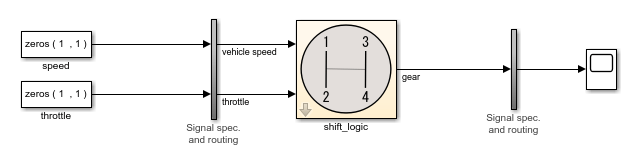
At the center of the harness is a copy of the shift_logic subsystem.
The shift_logic subsystem is the component under test. The two vertical
subsystems contain signal specification and routing.
The signal names used in the component under test propagate from the model to the test harness. For subsystem harnesses, some propagated signal names might be visible only after you compile the harness. For block diagram harnesses, signal names are propagated even if you do not select Show propagated signals in the Signal Properties dialog box.
You can also create a harness, or multiple harnesses at the same time by using the
sltest.harness.create function, the sltest.testmanager.createTestForComponent function, or the Create Test for
Model Component wizard, which is available in the Test Manager. For information on the
wizard, see Generate Tests and Test Harnesses for a Model or Components.
For information on test harness architecture, see Test Harness Construction for Specific Model Elements. For information on customizing the default harness settings when you create a new harness, see Customize Test Harness Creation Default Property Values.
Simulate the Test Harness
Assign values to the Constant blocks to test the component:
Change the value of the speed block to
50.Change the value of the throttle block to
30.Click Run in the Simulation tab to simulate the harness.
Open the scope and look at the result. The shift controller selects third gear.

Test Using the Test Manager
In the previous case, you supplied test inputs with Constant blocks. You can also use test inputs from external data files.
Create a test harness that uses Inport sources.
Create a test case that uses the test harness as the System Under Test.
Map external inputs to the test case.
Using a test case in the Test Manager allows you to iterate with different test vectors, add test cases, run batches of test cases, and organize your results. This example shows you how to use external data with a test harness, and simulate from the Test Manager.
To open the Test Manager, on the Apps tab, under Model Verification, Validation, and Test, click Simulink Test. Then, on the Tests tab, click Simulink Test Manager.
Select New > Test File from the Test Manager Toolstrip.
Name the file
ShiftLogicTest.Select New Test Case 1. In the System Under Test section, click Use current model
 .
.For Test Harness, select
ShiftLogic_InportHarnessfrom the drop down list. The test harness already exists in the model.In the Inputs section, click Create. Name the input data file
shift_logic_inputand select MAT file format.In the Signal Editor, enter the values for the inputs:
Select the speed signal and enter
50for times0and30. Press Enter to update the plot.Select the throttle signal and enter
30for times0and30. Press Enter to update the plot.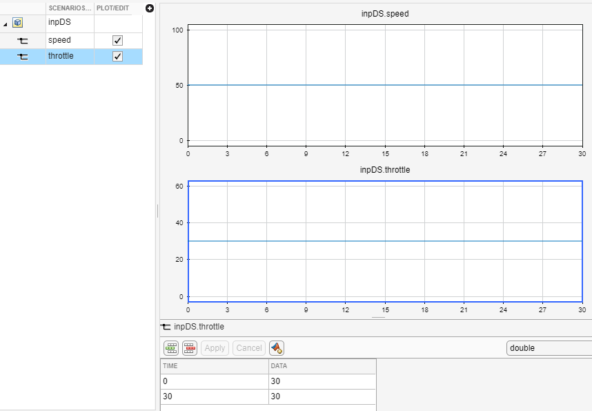
Click Save in the Signal Editor Toolstrip.
Select output data to capture.
In the Simulation Outputs section of the Test Manager, click Add.
In the test harness block diagram, select the
gearsignal line. Select the signal in the Connect dialog box.Click Done to add the signal to the test case outputs.
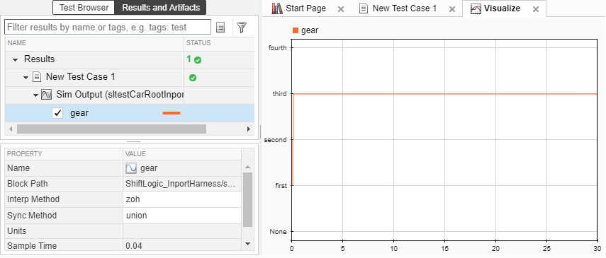
Click Run in the Test Manager Toolstrip.
Expand the results and highlight the gear signal output. The plot shows the controller selects third gear.