Asynchronous Message Handling in Adaptive Cruise Control
This example shows how to model an event-based adaptive cruise control (ACC) system using messages and message-triggered subsystems to reduce communication traffic and increase system efficiency. Components representing the physical system and control logic are simplified to show how sensory events can asynchronously trigger the ACC system. The model includes a front radar. The radar detects the distance between the vehicle and the vehicle ahead and identifies events for braking and acceleration. Then, the radar sends messages (in adaptive AUTOSAR this corresponds to adaptive events) to the ACC system. The ACC system converts messages to control signals and sends them to the brake actuator and powertrain to control the breaking and acceleration of the vehicle. The model allows you how to manually brake or accelerate and observe the vehicle speed and engine rpm. For more information about messages, see Simulink Messages Overview.
Using this model, you can generate adaptive AUTOSAR code for the ACCModule component when you open the component as a top model. The DistanceSensorModule (inside FrontRadarSensor), BrakeControlModule (inside BrakeActuator), and PowertrainControlModule (inside Powertrain) components can generate classic AUTOSAR code when you open them as the top model. These reference models are highlighted with blue.
For more information about modeling adaptive cruise control logic, see Collision Avoidance Assistance (Automated Driving Toolbox).
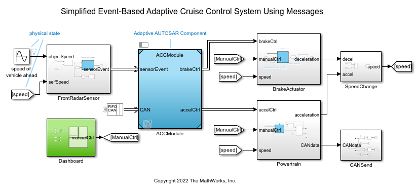
Adaptive Cruise Control Module
In the model, the ACCModule component is subscribed to sensor (radar) events. The ACCModule has two Message Triggered Subsystem blocks, Brake Event Handler and Acceleration Event Handler. The subsystems respond to the braking and acceleration events asynchronously. In real applications, invoking event handlers is usually done by message middleware, and the order of execution can be random depending on the environment. However, in simulations, you can schedule the execution of your model partitions and generate deterministic results. To test the behavior of your model for various simulation scenarios, change the order of execution of your model partitions. To create such model partitions in this model, Message Triggered Subsystem blocks are used in scheduled mode. In scheduled mode, you can schedule the execution of the subsystems as aperiodic partitions using the Schedule Editor. The subsystems pull and process the data based on a schedule instead of periodic execution, which reduces communication traffic and increases system efficiency.
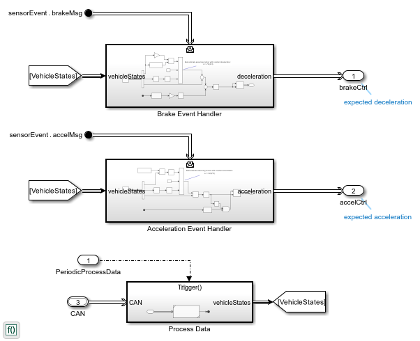
In the ACCModule component, the Function-Call Subsystem Process Data periodically reads the CAN bus and generates the data of vehicle states. The data is used by the two Message Triggered Subsystems Brake Event Handler and Acceleration Event Handler. You can set the period of the Process Data component by using the Sample time parameter of the root Inport block.
The ACCModule component is an export-function model. This modeling pattern also allows you to generate code for independent functions that can be integrated with an external environment and scheduler. For more information about export-function models, see Export-Function Models Overview. Because the ACCModule component is an AUTOSAR adaptive software component, it acts as message middleware and can generate code to be asynchronously triggered via the AUTOSAR adaptive platform.
Schedule Message-Triggered Subsystem Execution Using Schedule Editor
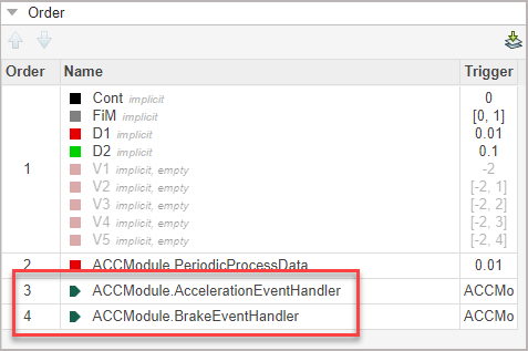
Open the Schedule Editor to observe the partitions of the model, including the message-triggered subsystems ACCModule.AccelerationEventHandler and ACCModule.BrakeEventHandler. For more information about the Schedule Editor tool, see Using the Schedule Editor.
You can use the Schedule Editor tool to change the order of the execution of the partitions so that when multiple partitions (tasks) are scheduled to be executed at the same time, the higher priority task is executed first. If a lower priority task is already running, the higher priority task preempts the lower priority one.

Simulate Model and Review Results
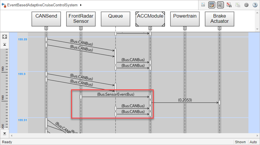
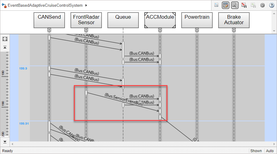
Simulate the model. Open the Sequence Viewer tool to observe the interchange of messages and event triggering between the blocks and components in your model. Also, you can see the order of the interchanges based on the current order of execution priority. In the current order, the ACCModule.AccelerationEventHandler and the ACCModule.BrakeEventHandler partitions have higher priority. The message from FrontRadarSensor with the SensorEventBus payload is transitioned to the ACCModule component and triggers the corresponding Message Triggered Subsystem prior to the CANBus messages as shown in the red box. For more information about the Sequence Viewer tool, see Use the Sequence Viewer to Visualize Messages, Events, and Entities.
You can change the order of priority so that the asynchronous event handlers have lower priority. In this order, Process Data subsystem executes first and provides the latest vehicle state to the message triggered subsystems.
If you simulate the model again, you can observe that the transition from FrontRadarSensor to ACCModule occurs after the CANBus messages.
Review Results of Simulation
Open the Dashboard component to manually control the vehicle and review the results.
The Monitor Panel shows the speed of the vehicle and the speed of the vehicle ahead. It also displays the distance between the vehicles.
The Control Panel allows you to manually stop or accelerate the vehicle. You can also specify the target distance between the vehicles at the equilibrium along with the expected deviation.
Gauges display the engine rpm and the vehicle speed in mph.

Use Manual Break Pedal
Simulate the model again. Press the Brake Pedal in the Control Panel after 50 seconds. Release the pedal around 150 seconds. Observe the vehicle speed and distance between the vehicles during and after your manual brake.
