간단한 마스크 만들기
마스크 편집기를 사용하여 대화형 방식으로 블록을 마스크 처리하거나 프로그래밍 방식으로 마스크 처리합니다. 이 예제에서는 마스크 편집기를 사용하여 블록을 마스크 처리하는 방법을 설명합니다. 프로그래밍 방식으로 블록을 마스크 처리하려면 Control Masks Programmatically 항목을 참조하십시오.
1단계: 마스크 편집기 열기
1. 블록을 마스크 처리할 모델을 엽니다. 직선 방정식  에 대한 Subsystem 블록이 포함된 모델이 있다고 가정하겠습니다.

2. Subsystem 블록을 선택하고 Subsystem 블록을 마우스 오른쪽 버튼으로 클릭한 다음 마스크 만들기를 클릭합니다.

2단계: 마스크 정의하기
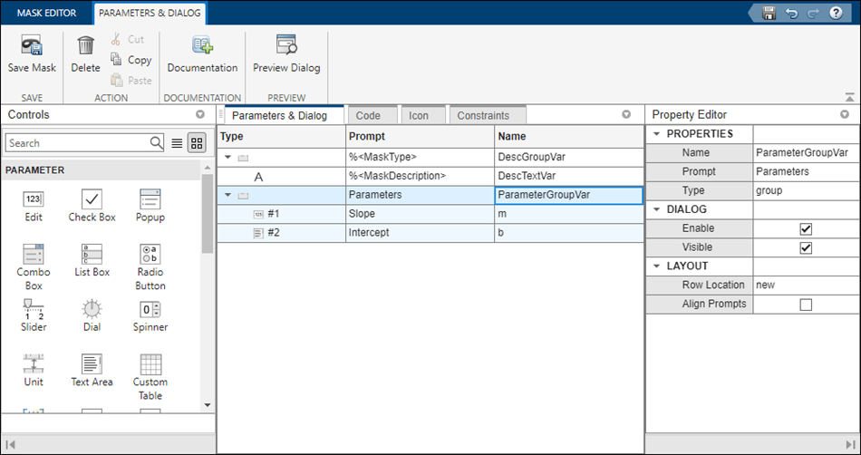
마스크 편집기에는 블록 마스크를 정의하고 마스크의 대화 상자를 사용자 지정할 수 있는 4개의 탭이 있습니다. 각 창에 대한 자세한 내용은 Mask Editor Overview 항목을 참조하십시오. 파라미터 및 대화 상자 탭을 사용하여 파라미터, 디스플레이, 동작 항목과 같은 컨트롤을 마스크 대화 상자에 추가할 수 있습니다.
1. 왼쪽 창에 있는 파라미터에서 편집 파라미터를 블록 마스크에 추가합니다. 편집을 두 번 클릭하여 대화 상자 창에 새로운 행을 두 개 추가합니다.
2. 두 개의 편집 파라미터에 대해 프롬프트 열에 Slope 및 Intercept를 입력합니다. 프롬프트 열에 입력한 값이 마스크 대화 상자에 표시됩니다. 마찬가지로 이름 열에 m 및 b를 입력합니다. 이름 열에 입력하는 값이 마스크 파라미터 이름입니다. 마스크 파라미터 이름은 유효한 MATLAB® 이름이어야 합니다.
3. 오른쪽 창에 있는 속성 편집기에서 속성, 대화 상자, 레이아웃 섹션에 값을 입력합니다.
4. 마스크 저장을 클릭합니다.

5. 마스크 편집기를 종료하지 않고 마스크 대화 상자를 미리 보려면 미리보기를 클릭합니다.
참고: Simulink® 마스크 파라미터는 동일한 마스크에 있는 또 다른 파라미터를 참조할 수 없습니다.
자세한 내용은 Parameters & Dialog Pane 항목을 참조하십시오.
코드 창을 사용하여 마스크 파라미터를 제어하는 MATLAB 코드를 지정합니다. 예를 들어, 마스크 파라미터에 대해 미리 정의된 값을 제공할 수 있습니다. 이 예에서는 방정식  를 살펴보겠습니다.
 m에 해당하는 자식 블록의 값을 설정하려면 코드 창에서 set_param 함수를 사용하면 됩니다.
자세한 내용은 Code Pane 항목을 참조하십시오.
아이콘 탭을 사용하여 블록 마스크에 대한 아이콘을 만듭니다. 마스크 편집기는 블록 아이콘을 작성하는 두 개의 모드를 제공합니다.
그래픽 아이콘 편집기: 그래픽 환경을 통해 블록의 마스크 아이콘을 만들고 편집할 수 있습니다. 그래픽 아이콘 편집기의 다양한 기능이 아이콘을 손쉽게 만들 수 있도록 도와 줍니다. 마스크 편집기에서 그래픽 아이콘 편집기를 시작하십시오. 자세한 내용은 Graphical Icon Editor Overview 항목을 참조하십시오.
마스크 그리기 명령: 마스크 그리기 명령 세트를 사용하여 마스크 처리된 블록 아이콘을 만들 수 있습니다. 왼쪽의 속성 창을 사용하여 아이콘 속성과 아이콘 가시성을 지정할 수 있습니다. 자세한 내용은 Icon drawing commands 항목을 참조하십시오.
제약 조건 탭을 사용하면 사용자가 직접 검증 코드를 작성할 필요 없이 마스크 파라미터에 대한 검증을 만들 수 있습니다. 제약 조건에는 파라미터 제약 조건, 상호 파라미터 제약 조건, 포트 제약 조건, 상호 포트 제약 조건의 네 가지 유형이 있습니다. 자세한 내용은 Constraints 항목을 참조하십시오.
3단계: 마스크에 대해 연산 수행하기
1. 마스크를 미리 보고 블록 마스크 해제 또는 블록 마스크 편집을 선택할 수 있습니다.
2. 마스크 처리된 블록을 더블 클릭합니다.

3. 마스크 대화 상자의 Slope 상자와 Intercept 상자에 값을 입력합니다. 출력을 보려면 모델을 시뮬레이션합니다.
4. 확인을 클릭합니다.
5. 마스크 정의를 편집하려면 Subsystem 블록을 선택하고 마우스 오른쪽 버튼을 클릭한 다음 마스크 > 마스크 편집을 선택합니다.
6. Subsystem 블록을 선택하고 마우스 오른쪽 버튼을 클릭한 다음 마스크 > 마우스 내부 탐색을 선택하여 마스크 처리된 서브시스템 내부의 블록을 확인합니다.