주요 콘텐츠

MultiStateImage

Display image reflecting input value

  • MultiStateImage block

Libraries:
Simulink / Dashboard

Description

The MultiStateImage block displays an image to indicate the value of the input signal. You can use the MultiStateImage block with other Dashboard blocks to build an interactive dashboard of controls and indicators for your model. You can specify pairs of input values and images to provide the information you want during simulation.

Connect Dashboard Blocks

Dashboard blocks do not use ports to connect to model elements. To connect a dashboard block, use connect mode. To enter connect mode on an unconnected block, pause on the block you want to connect and click the Connect button . To enter connect mode on a connected block, select the block, pause on the ellipsis that appears (…), and in the action menu that expands, click the Connect button.

To connect a display block to a signal in your model or change the connection of a display block, enter connect mode. Select the signal line to which you want to connect. From the list that appears, select the signal to which you want to connect. Then, pause on the dashboard block and click the Done Connecting button . To see the dashboard block display the value of the connected block, run the simulation.

For more information about connecting dashboard blocks, see Connect Dashboard Blocks to Simulink Model.

You can also connect dashboard blocks to a Stateflow® chart. For more information, see Connect Dashboard Blocks to Stateflow (Stateflow).

This animation shows how to connect the MultiStateImage block to your model.

An unconnected MultiStateImage block connects to the signal that a Pulse Generator block sends to a Display block.

Examples

expand all

The model MultiStateImagePulse contains a Pulse Generator block connected to a Display block. The Pulse Generator block generates a square wave pulse with an amplitude of 1 every other second. A MultiStateImage block is connected to the pulseSig signal. The block is configured to display the image of an up arrow when the signal has a value of 1 and a down arrow when the signal has a value of 0.

The Block Parameters dialog box for the MultiStateImage

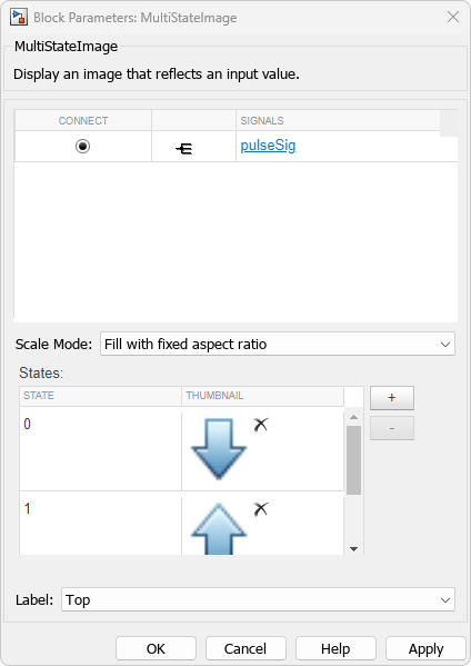
Simulate the model. During simulation, the MultiStateImage block displays an up arrow when the Pulse Generator block generates a pulse and a down arrow when no pulse occurs.

Animation of the MultiStateImagePulse model during simulation

Limitations

  • Except for the Dashboard Scope block and the Display block, dashboard blocks can only connect to real scalar signals.

  • You cannot use the Connection table in the Block Parameters dialog box to connect a dashboard block to a block that is commented out. When you connect a dashboard block to a commented block using connect mode, the dashboard block does not display the connected value until the you uncomment the block.

  • Dashboard blocks cannot connect to model elements inside referenced models.

  • When you simulate a model hierarchy, dashboard blocks inside referenced models do not update.

  • Dashboard blocks do not support rapid accelerator simulation.

  • During simulation, you cannot connect a dashboard block to Stateflow chart data or state activity.

  • You cannot programmatically connect a dashboard block to Stateflow chart data or state activity.

  • Some signals do not have data available during simulation due to block reduction or optimization for accelerator mode simulations. To view such a signal using a dashboard block, mark the signal for logging.

Parameters

expand all

This block is a display block — a block that displays a signal value. Connect the block to the signal you want to display.

Dashboard blocks do not use ports to connect to model elements. To connect a dashboard block, use connect mode, the Simulink® Toolstrip, or the Connection table in the Block Parameters dialog box. For information, see Connect Dashboard Blocks to Simulink Model.

To connect to a signal using Connection table:

  1. Select the block.

  2. In the Property Inspector, on the Parameters tab, click Connect or Change.

  3. Select the signal line to whose signal you want to connect.

  4. In the table that appears, select the signal.

  5. Click Apply.

You can also connect dashboard blocks to a Stateflow chart. For more information, see Connect Dashboard Blocks to Stateflow (Stateflow).

Programmatic Use

You can programmatically connect a display block to a signal. Define a Simulink.HMI.SignalSpecification object that represents the signal. Then, set the value of the Binding parameter to the object. To set the value of the Binding parameter, use the set_param function.

For example, suppose the model named vdp contains a Circular Gauge block named myGauge and a signal named x1. To connect the block to the signal, use this code.

blockPath = "vdp/myGauge";
signalPath = "vdp/x1";

myObj = Simulink.HMI.SignalSpecification;
myObj.BlockPath = Simulink.BlockPath(signalPath);

set_param(blockPath,Binding=myObj)
Parameter: Binding
Values: Simulink.HMI.SignalSpecification object

Example: set_param(gcb,Binding=myObj)

Specify how to scale the image.

Fill with fixed Aspect Ratio scales the image to the size of the block while retaining its original aspect ratio.

Fixed displays the image with its fixed true size.

Fill adjusts the image to fill the block.

Programmatic Use

To set the block parameter value programmatically, use the set_param function.

Parameter: ScaleMode
Values: 'Fill with fixed aspect ratio' (default) | "Fill with fixed aspect ratio" | "Fixed" | "Fill"

Example: set_param(gcb,ScaleMode="Fill")

States match an image to display with a value of the connected variable or parameter. Each state consists of a State and an image, displayed as a Thumbnail in the States table for the MultiStateImage block.

  • State — Connected variable or parameter value that causes the MultiStateImage block to display the corresponding image.

  • Thumbnail — Image to display when the connected variable or parameter value matches the corresponding State.

Click the + button to add another state.

Programmatic Use

To set the block parameter value programmatically, use the set_param function.

Specify the value of the States parameter as an array of structures, where each structure represents a state. Each structure contains these fields:

  • State — Value of the connected signal that causes the block to enter the state.

  • Size1-by-2 vector containing the width and height for the image in that order, in pixels, specified as a uint64.

  • Image — Character array of Base64 encoded image data.

  • Thumbnail — Character array of Base64 encoded image data for the thumbnail image to display in the States table in the block dialog box.

For example, suppose you want the currently selected Multistate Image block to have two states. For the first state, the character arrays of the image and thumbnail data are stored in the variables myBase64Image and myBase64Thumbnail. For the second state, the character arrays are stored in the variables myBase64Thumbnail and myBase64Thumbnail. To implement these states, use this code.

state1.State = 1;
state1.Size = [uint64(400) uint64(400)];
state1.Image = myBase64Image;
state1.Thumbnail = myBase64Thumbnail;
state2.State = 2;
state2.Size = [uint64(400) uint64(400)];
state2.Image = myBase64Image2;
state2.Thumbnail = myBase64Thumbnail2;

myStates = [state1 state2];

set_param(gcb,States=myStates)
Parameter: States
Values: N-by-1 struct array, where N is the number of states and each struct has the fields State, Size, Image and Thumbnail

Example: set_param(gcb,States=myStates)

The block displays the default image when the connected signal value does not correspond to any of the specified states. Specify the DefaultImage parameter as a structure containing the fields:

  • Size1-by-2 vector containing the width and height for the image in that order, in pixels, specified as uint64.

  • Image — Character array of Base64 encoded image data.

  • Thumbnail — Character array of Base64 encoded image data for the thumbnail image to display in the States table in the block dialog box.

Parameter: DefaultImage
Values: struct with the fields Size, Image and Thumbnail

Example: set_param(gcb,DefaultImage=myDefault)

Position of the block label. When the block is connected to an element in the model, the label is the name of the connected element.

Programmatic Use

To set the block parameter value programmatically, use the set_param function.

Parameter: LabelPosition
Values: 'Top' (default) | "Top" | "Bottom" | "Hide"

Example: set_param(gcb,LabelPosition="Bottom")

Block Characteristics

Data Types

Boolean | double | enumerated | fixed point | half | integer | single

Direct Feedthrough

no

Multidimensional Signals

no

Variable-Size Signals

no

Zero-Crossing Detection

no

Extended Capabilities

expand all

Version History

Introduced in R2016b

expand all