Model Feedback Control System
This example shows how to model a feedback control system using Simulink® signals that carry matrix and vector representations of different components of the feedback system. In this example, the controller is designed for a buck-boost converter to track a reference voltage signal. Buck-boost converters are extensively used in distributed power supply systems and modern power electronics devices due to their high efficiency, high power density, low cost, and compact size.
Open the model.
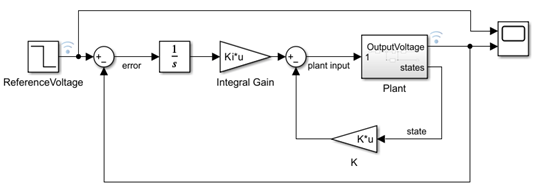
open_system('FeedbackMatrix.slx')The model represents a closed-loop system where a buck-boost converter achieves the reference voltage profile using a controller that uses the state feedback.

Buck-boost Converter
The state-space equations represent the buck-boost converter:
represents the inductor current and capacitor voltage, respectively and represents the output voltage.
Open the Plant subsystem to view the buck-boost converter model.
open_system('FeedbackMatrix/Plant')
In this example:
, , and .
Controller
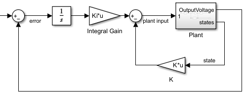
During the simulation, the controller uses the error and state signal values and computes the plant input (plant input) that drives the plant output towards the reference signal.
In this example, the controller consists of a linear quadratic regulator (LQR) represented by the gain vector K in the feedback path and an integral gain represented by Ki in the feedforward path. The lqr command computes the controller parameters for the desired pole locations. The first element of the LQR gain vector is used as the integral gain Ki in the feedforward path and the other two elements are concatenated in the gain vector K, which is used in the feedback path.
The model loads the controller parameters from the mdlParams.mat file.

Results
Simulate the model and visualize the results using a Scope block. The plant output signal Voltage tracks the reference signal, which is a step signal with an initial value of 25 and final value of 12.
out = sim('FeedbackMatrix.slx');
See Also
Gain | Integrator | Subsystem
Topics
References
[1] Tan, Rodney H.G. and Landon Y.H. Hoo. "DC-DC converter modeling and simulation using state space approach."2015 IEEE Conference on Energy Conversion (CENCON)., IEEE, 2015, pp. 42-47. DOI.org (Crossref) https://doi.org/10.1109/CENCON.2015.7409511.
[2] Patri, Kishore Kumar, and Susovon Samanta. "State feedback with integral control for boost converter & its microcontroller implementation."2018 IEEMA Engineer Infinite Conference (eTechNxT), IEEE, 2018, pp. 1-5. DOI.org (Crossref) https://doi.org/10.1109/ETECHNXT.2018.8385374.