Translational Mechanical Converter (IL)
Interface between isothermal liquid and mechanical translational networks
Libraries:
Simscape /
Foundation Library /
Isothermal Liquid /
Elements
Description
The Translational Mechanical Converter (IL) block models an interface between an isothermal liquid network and a mechanical translational network. The block converts isothermal liquid pressure into mechanical force. Use this block to build linear actuators.
The converter contains a variable volume of liquid. If you select the Enable dynamic compressibility check box, then the pressure evolves based on the dynamic compressibility of the liquid volume. The Mechanical orientation parameter lets you specify whether an increase in pressure moves port R away from or towards port C.
Port A is the isothermal liquid conserving port associated with the converter inlet. Ports R and C are the mechanical translational conserving ports associated with the moving interface and converter casing, respectively.
Mass Balance
The mass conservation equations in the mechanical converter volume are
where:
is the mass flow rate into the converter through port A.
ε is the mechanical orientation of the converter (
1if increase in fluid pressure causes positive displacement of R relative to C,-1if increase in fluid pressure causes negative displacement of R relative to C).ρI is the fluid density inside the converter.
βI is the fluid bulk modulus inside the converter.
S is the cross-sectional area of the converter interface.
v is the translational velocity of the converter interface.
vR and vC are the translational velocities of ports R and C, respectively.
x is the displacement of the converter interface.
V is the liquid volume inside the converter.
Vdead is the dead volume, that is, volume of liquid when the interface displacement is 0.
pI is the pressure inside the converter.
If you connect the converter to a Multibody joint, use the physical signal input port p to specify the displacement of port R relative to port C. Otherwise, the block calculates the interface displacement from relative port velocities, according to the equations above. The interface displacement is zero when the liquid volume is equal to the dead volume. Then, depending on the Mechanical orientation parameter value:
If
Pressure at A causes positive displacement of R relative to
              C
, the interface displacement increases when the liquid volume increases from dead volume.If
Pressure at A causes negative displacement of R relative to
              C
, the interface displacement decreases when the liquid volume increases from dead volume.
Equations used to compute the fluid mixture density and bulk modulus depend on the selected isothermal liquid model. For detailed information, see Isothermal Liquid Modeling Options.
Momentum Balance
The momentum conservation equation in the mechanical converter volume is
where:
F is the force the liquid exerts on the converter interface.
penv is the environment pressure outside the converter.
Assumptions and Limitations
Converter walls are perfectly rigid.
The converter contains no mechanical hard stops. To include hard stops, use the Translational Hard Stop block.
The flow resistance between the inlet and the interior of the converter is negligible.
The kinetic energy of the fluid in the converter is negligible.
Examples
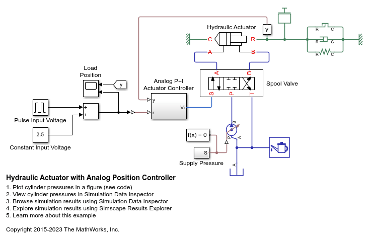
Hydraulic Actuator with Analog Position Controller
How the Foundation library can be used to model systems that span electrical, mechanical and isothermal liquid domains. In the model, a hydraulic system implemented in the isothermal liquid domain controls the mechanical load position in response to a voltage reference demand. If the reference demand is zero, then the hydraulic actuator (and load) displacement is zero, and if the reference is +5 volts, then the displacement is 100 mm.
Ports
Input
Conserving
Parameters
References
[1] Gholizadeh, Hossein, Richard Burton, and Greg Schoenau. “Fluid Bulk Modulus: Comparison of Low Pressure Models.” International Journal of Fluid Power 13, no. 1 (January 2012): 7–16. https://doi.org/10.1080/14399776.2012.10781042.
Extended Capabilities
Version History
Introduced in R2020a