Switch with Hysteresis
The Switch block in the Simscape™ Foundation library implements a switch controlled by an external physical
signal. The block uses an if-else statement. If the external physical
signal at the control port is greater than the threshold, then the switch is closed, otherwise
the switch is open.
This example implements a switch with hysteresis applied to the switching threshold level. The hysteresis acts to prevent rapid spurious switching when the control signal is noisy.
The switch has two distinct operating modes, shown in the diagram. If the external physical signal at the control port is greater than the upper threshold, then the switch is closed. If the signal is lower than the lower threshold, the switch is open.

The following component implements the logic in the diagram by using a mode chart.
component delayed_switch
% Switch with Hysteresis

inputs
    u = { 0.0, '1' };
end

nodes
    p = foundation.electrical.electrical; % +
    n = foundation.electrical.electrical; % -:right
end

parameters
    R_closed = { 0.01, 'Ohm' };   % Closed resistance R_closed
    G_open   = { 1e-8, '1/Ohm' }; % Open conductance G_open
    T_closed = { 0.5, '1' };      % Upper threshold
    T_open   = { 0, '1' };        % Lower threshold
    InitMode = switching.open;    % Initial Mode
end

variables
    i = { 0, 'A' }; % Current
    v = { 0, 'V' }; % Voltage
end

branches
    i : p.i -> n.i;
end

% Validate parameter values
equations
            assert( T_closed >= T_open, 'Upper threshold must be higher than Lower threshold' );
end

modecharts(ExternalAccess = observe)
    m1 = modechart
        modes
            mode CLOSED
                equations
                    v == p.v - n.v;
                    v == i*R_closed;
                end
            end
            mode OPEN
                equations
                    v == p.v - n.v;
                    v*G_open == i;
                end
            end
        end
        transitions
            CLOSED -> OPEN : u < T_open;
            OPEN -> CLOSED : u > T_closed;
        end
        initial
            OPEN : InitMode <= 0;
        end
    end

end

end
The mode chart m1 defines two modes, CLOSED and
OPEN. Each mode has an equations section that lists
all the applicable equations. The transitions section defines the
transitions between the operating modes, based on predicate conditions:
The switch transitions from
CLOSEDtoOPENwhen the control signal falls below the lower threshold,T_open.The switch transitions from
OPENtoCLOSEDwhen the control signal rises above the upper threshold,T_closed.
The initial section specifies the initial operating mode, based on a
predicate condition:
If the predicate is true (that is, the Initial Mode parameter value is less than or equal to 0), then the
OPENmode is active at the start of simulation.If the predicate is not true, then the
CLOSEDmode (the first mode listed in themodessection) is active at the start of simulation.
Note
The Initial Mode parameter uses an enumeration:
classdef switching < int32
   enumeration
     open (0)
     closed (1)
   end
   methods(Static)
       function map = displayText()
         map = containers.Map;
         map('open') = 'Switch is open';
         map('closed') = 'Switch is closed';
       end
   end
 end
For the component to work as described, this enumeration needs to be in a separate
switching.m file. The file can be located either on the MATLAB® path or in a namespace imported into the component. In general, enumerations
are very useful in mode charts, because they let you specify a discrete set of acceptable
parameter values. For more information, see Enumerations.
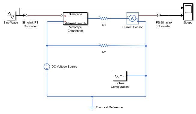
To verify the correct component behavior, deploy it in a Simscape Component block. Create a simple test model, as shown, with all the blocks using the default parameter values.


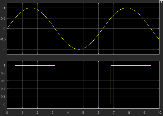
Simulate the model with the default values.

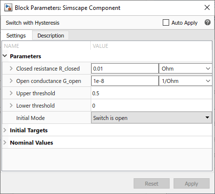
The Initial Mode parameter value is Switch is
open. This enumerated value evaluates to 0, which makes the predicate in the
initial section true. Therefore, at the start of simulation the switch is
open and no current flows through the resistor R1. When the control signal value reaches 0.5
(the Upper threshold parameter value), the switch closes and the current
through the branch, based on the other parameter values, is 1A. When the control signal falls
below 0 (the Lower threshold parameter value), the switch opens.
Now change the Initial Mode parameter value to Switch is
closed and simulate the model. The enumerated value evaluates to 1, the
predicate condition in the initial section is no longer true, and therefore
the first mode listed in the modes section is active. At the start of
simulation, the switch is closed, and it stays closed until the control signal falls below 0.

See Also
modecharts | modes | transitions | initial