Busbar
R2026bLoad flow analysis busbar connector
Busbar block

To add a block to a model, double-click the canvas and start typing the block name. Then, select the block from the list.
Libraries:
Simscape /
Electrical /
Connectors & References
Description
The Busbar block is a connector for load-flow analysis. Use this block with three-phase Simscape™ Electrical™ networks that are compatible with frequency-time simulation mode. After completing simulation, the block adds an annotation showing the voltage, phase, active power, and reactive power at each of its three-phase electrical conserving ports at the time the simulation started. For the annotation to be added, Simscape logging must be enabled.
The block simulates in time-based simulation mode and displays an annotation with
initial values. If the network is compatible with frequency-time simulation mode and, in
the Solver Configuration block, you select the Start
simulation from steady state parameter, then the annotation reflects
the initial conditions computed from the load‑flow analysis. If you clear the
Start
				simulation from steady state
parameter, then the annotation still displays initial values, but these values do not
represent load‑flow results. In time-based simulation mode, the block computes
approximate values for voltage, phase, and active and reactive power. You can access
these values through Simscape logging or by enabling the optional measurement ports on the block. The
accuracy of these values depends on the level of system balance and the harmonic
content.
Examples
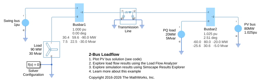
2-Bus Loadflow
A model of a two-bus three-phase power system network. The model uses three instances of the Load Flow Source block from Simscape™ Electrical™, one configured to be the swing bus, one configured to be the PV bus, and one configured to be the PQ load. The PV bus regulates its output to be at a voltage of 1.025 times rated voltage and to deliver 80MW active power to the network. The Swing bus regulates voltage at the other end of the transmission line to be one times rated voltage, and it delivers the requisite power to the network so that overall active and reactive powers balance. The Simscape initialization solver determines the required internal initial voltage amplitudes and phases in both the PV bus and the Swing bus so as to start in steady state.
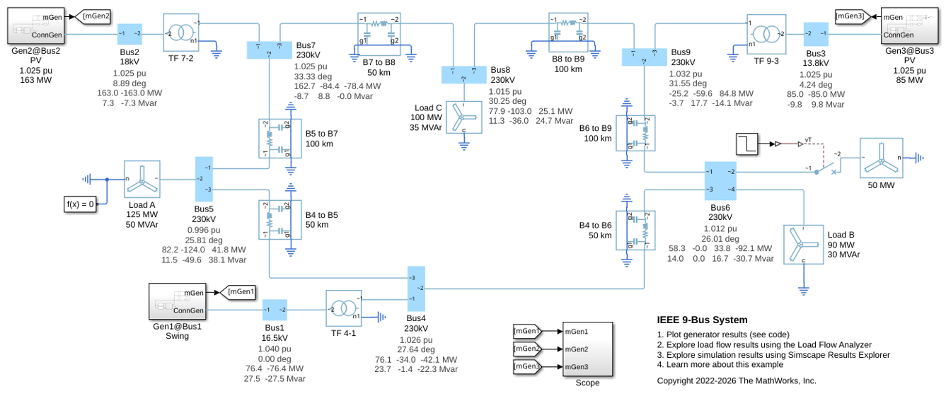
IEEE 9-Bus System
Model a 9-bus three-phase power system network. This example is based on the IEEE® benchmark test case. For more information, see "Power System Control and Stability" by P. M. Anderson and A. A. Fouad (IEEE Press, 2003).
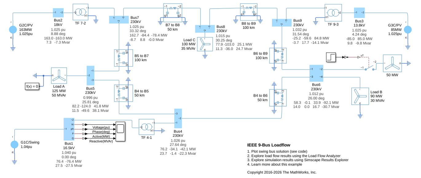
IEEE 9-Bus Loadflow
A model of a 9-bus three-phase power system network. This example is based on an IEEE® benchmark test case, further details of which can be found in "Power System Control and Stability" by P. M. Anderson and A. A. Fouad (IEEE Press, 2003). Simscape™ initializes two of the generators to the specified powers and terminal voltages, and initializes the remaining swing bus generator to meet just the specified voltage. The resulting load flow solution is appended to each of the busbars post-simulation. The four rows correspond to per-unit voltage, phase, active power, and reactive power respectively. Looking at Bus 1, it can be seen from the annotation that the swing generator delivers 76.4MW of active power and 27.5MVAr or reactive power to the network. Differences to the original benchmark are due to the transmission line models and transformer configurations used.
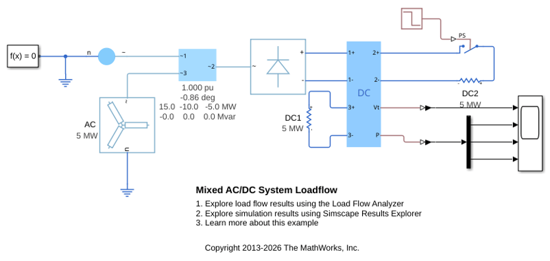
Mixed AC/DC System Loadflow
Use the Load Flow Analyzer to review the load flow results of a mixed AC/DC system. The model to which this analysis is applied includes an AC load flow source, a three-phase rectifier, and three loads. One of the loads is AC, one is permanently connected on the DC side, and one is switched on the DC side.
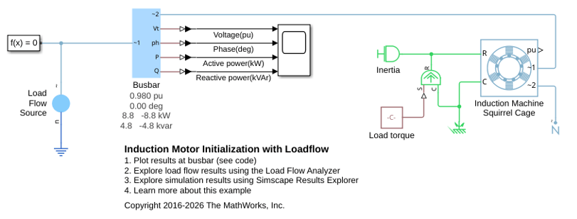
Induction Motor Initialization with Loadflow
Initialize a three-phase induction motor as part of a load flow analysis. When initializing an induction machine that is directly connected to an AC network, in steady state there is one degree of freedom which you can set by any one of shaft torque, shaft power, motor speed, or electrical power.
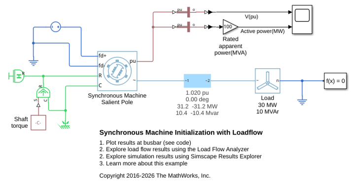
Synchronous Machine Initialization with Loadflow
Initialize synchronous machine as part of a load flow analysis. When initializing a synchronous machine there are two degrees of freedom which can be set by any two of rotor angle, active power, reactive power and terminal voltage. The pair of variables that are constrained is set by the source type drop-down menu, this having options of Swing bus, PV bus and PQ bus. Here the machine is configured for a swing bus with a 1.02 per-unit voltage and zero degrees phase.
Ports
Output
Conserving
Parameters
Extended Capabilities
Version History
Introduced in R2019b

