Design IBIS-AMI Models to Support Clock Forwarding
This example shows how to create Rx AMI models that support clock forwarding as defined in the IBIS 7.1 specification by modifying the library blocks in SerDes Toolbox™. This example will use a DDR5 write transfer (Controller to SDRAM) to demonstrate the setup.
Background
The IBIS 7.1 specification adds the ability pass in an external clock signal, either as a waveform or clock-times, to a data IBIS-AMI receiver GetWave model, using the clock_times pointer as defined in the IBIS specification. A new AMI Reserved Parameter, Rx_Use_Clock_Input, is used to enable this functionality.
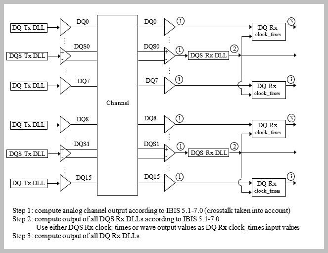
The figure below shows a typical DDR5 coupled channel simulation setup using clock-forwarding. The clock times or waveform generated by DQS0 is passed to DQ[7:0] (DQ0, DQ1... DQ7) using the DQ Rx DLL’s clock_times pointer. The DQ Rx DLL then operates on these clock times as desired (for example triggering DFE taps, modeling the DQS clock delay tree or centering the DQ on the DQS waveform) and then passes out the same or modified clock_times as usual. This same process is repeated for DQS1 and DQ[8:15].
This example provides an introduction to clock-forwarding in SerDes Toolbox and shows how to use various Simulink® tools and MATLAB® functions to generate and test an IBIS-AMI executable that supports clock-forwarding. It does not provide a specific clock-forwarding algorithm.
Tx/Rx IBIS-AMI Model Generation in SerDes Designer App
The first part of this example sets up the target transmitter and receiver architectures using the SerDes Designer app. The SerDes system is then exported to Simulink where clock-forwarding will be added and explored. Finally, a spec-compliant IBIS-AMI model will be generated for use in any IBIS 7.1 compliant EDA tool.
Type the following command in the MATLAB command window to open the dq_clock_forward model in SerDes Designer:
>> serdesDesigner('dq_clock_forward')

The transmitter (Tx) uses a 4-tap FFE. The receiver (Rx) will use a DFE and CDR that supports clock-forwarding. Since clock forwarding is a time-domain only feature, a dedicated DFEClkFwd block will be added later after exporting the SerDes system to Simulink.
Configuration Setup
Symbol Time is set to
200.0ps (5.0Gbps)Target BER is set to
1e-16.Signaling is set to
Single-ended.Samples per Symbol and Modulation are kept at default values, which are
16andNRZ(nonreturn to zero), respectively.
Transmitter Model Setup
The Tx FFE block uses four taps: one pre-tap, one main-tap, and two post-taps.
The Tx AnalogOut model is set up so that Voltage is
1.1V, Rise time is10ps, R (output resistance) is50 ohms, and C (capacitance) is0.65pF.
Channel Model Setup
Single-ended impedance is set to
40ohms.Target Frequency is set to
2.5GHz, which is the Nyquist frequency for 5.0 GHz.Channel loss is set to
5dB at Nyquist, which is typical of DDR channels.
Receiver Model Setup
The Rx AnalogIn model is set up so that R (input resistance) is
40Ohms and C (capacitance) is0.65pF.A dedicated DFECDR block that supports clock forwarding will be added later.
Export SerDes System to Simulink
Click on the Export button to export the configuration to Simulink for customization and generation of the AMI model executables.
Rx IBIS-AMI Model Setup in Simulink
The second part of this example takes the SerDes system exported by the SerDes Designer app and customizes it as required for clock-forwarding in Simulink.
Review Simulink Model Setup
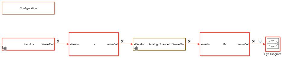
The SerDes System imported into Simulink consists of Configuration, Stimulus, Tx, Analog Channel and Rx blocks. All the settings from the SerDes Designer app have been transferred to the Simulink model. Note that since clock-forwarding is only implemented in the Rx, the Tx block will be untouched in this example.
Rx Block Setup for Clock-Forwarding
Double-click on the Rx block to push into the Rx-subsystem. Using the Library Browser, navigate to Library->SerDes Toolbox->Datapath Blocks and drag the DFEClkFwd block onto the canvas. Alternatively, you can left-click on the canvas and type "DFEClkFwd" to quickly add the DFEClkFwd block. Connect this block to the WaveIn and WaveOut ports.

Adding Rx AMI Parameter Rx_Use_Clock_Input
When the DFEClkFwd block is added to the Rx datapath, the Rx AMI parameter Rx_Use_Clock_Input is automatically added to the Rx AMI tree. If needed, this parameter can also be manually added to the Rx AMI model by clicking on the Reserved Parameters... button and checking the box next to Rx_Use_Clock_Input.
Run Refresh Init
While clock-forwarding is a time-domain only parameter, in order to enable the DFE and CDR in Init (for Statistical simulations) you must run Refresh Init after adding the DFEClkFwd block. In the Rx sub-system, double click on the Init block, then click on the Refresh Init button.

Review DFEClkFwd Block Setup
The DFEClkFwd block contains standard SerDes Toolbox DFE and CDR system objects, a clock-forwarding CDR and a CDR output selector. When the clock-forwarding parameter Rx_Use_Clock_Input is set to "None", the standard CDR is used. When Rx_Use_Clock_Input is set to "Times" or "Wave", the clock-forwarding CDR is used to pass in clock times or a waveform from an external AMI model. This block also supports PAMn signaling.
Double-clicking on the DFEClkFwd block will bring up the default setup. The DFE is set up for four DFE taps. The Initial tap weights are set to 0, the Minimum tap values are set to [-0.2 -0.075 -0.06 -0.045] V, and the Maximum tap values are set to [0.05 0.075 0.06 0.045] V. Finally, the 2x tap weights option is selected to make the DFE tap values compliant with the JEDEC specification.
Run Simulink Model
The Simulink model is now ready to run. Press the run button to launch the simulation.
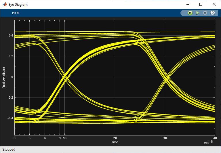
As the simulation runs, the Time Domain eye diagram gets constantly updated:
After the simulation is complete, the Init Statistical and Time Domain Analysis Results plot becomes available:
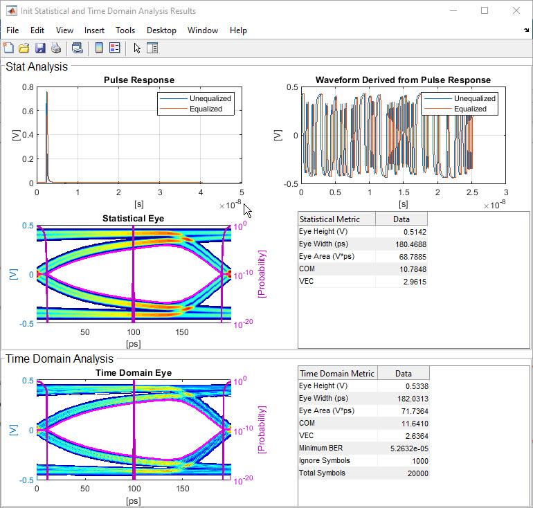
Note that since clock-forwarding only affects the Time Domain results, the Statistical results will not reflect the effects of clock-forwarding.
Controlling Clock-Forwarding Simulations
There are two AMI parameters, Rx_Use_Clock_Input and ForwardClockOffset that control the operation of clock forwarding in the Rx AMI model. In addition, there are a number of options for generating a clock or strobe waveform that can be used to test the Rx AMI model as follows.
Changing Current Value of Rx_Use_Clock_Input
The operation of the clock forwarding is controlled by the reserved AMI parameter Rx_Use_Clock_Input. When Rx_Use_Clock_Input is set to "None", the standard CDR is used. When set to "Times", the in-coming clock times are used directly. When set to "Wave", the in-coming waveform is converted to clock times using a zero-crossing detector. These clock times are used to determine when to apply the DFE taps, then are passed unchanged to the IBIS-AMI clock_times block to generate the normal clock times out for use by the EDA tool.
To change the value of Rx_Use_Clock_Input, use the AMI-Rx tab of the SerDes IBIS-AMI Manager.

Setting Clock Offset
The input AMI parameter ForwardClockOffset is included in the DFEClkFwd block. This parameter is of type Integer, with a Default of 0 and a Range of 0 to 1024. In the DFEClkFwd block, this parameter is used to delay the incoming clock times by up to 1024 samples. Using the SerDes IBIS-AMI Manager you can use this delay to adjust the location of the external clock with respect to the data waveform as desired.
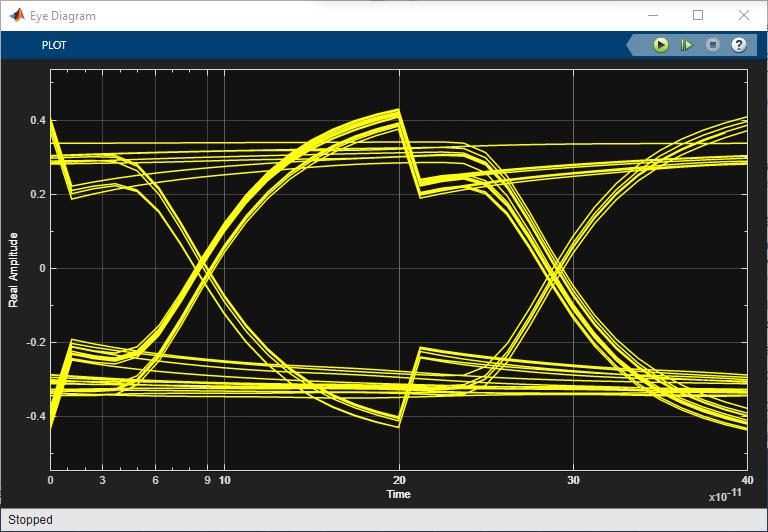
For example, here is the time domain eye diagram with DFE Tap 1 set to -0.100, Rx_Use_Clock_Input set to Wave and ForwardClockOffset set to 0:
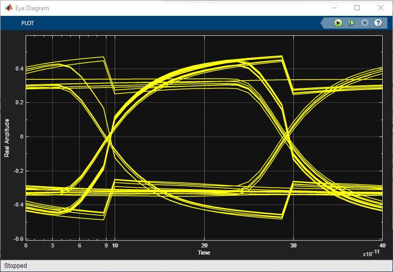
Note how the DFE taps are being applied in the center of the eye instead of at the edges of the eye. With the ForwardClockOffset delay set to 7, the DFE taps are being applied at the ideal location at the edge of the eye:
Note: Delay values less that 0 will have no effect on the resulting waveform.
Generating Clock and Strobe Waveforms
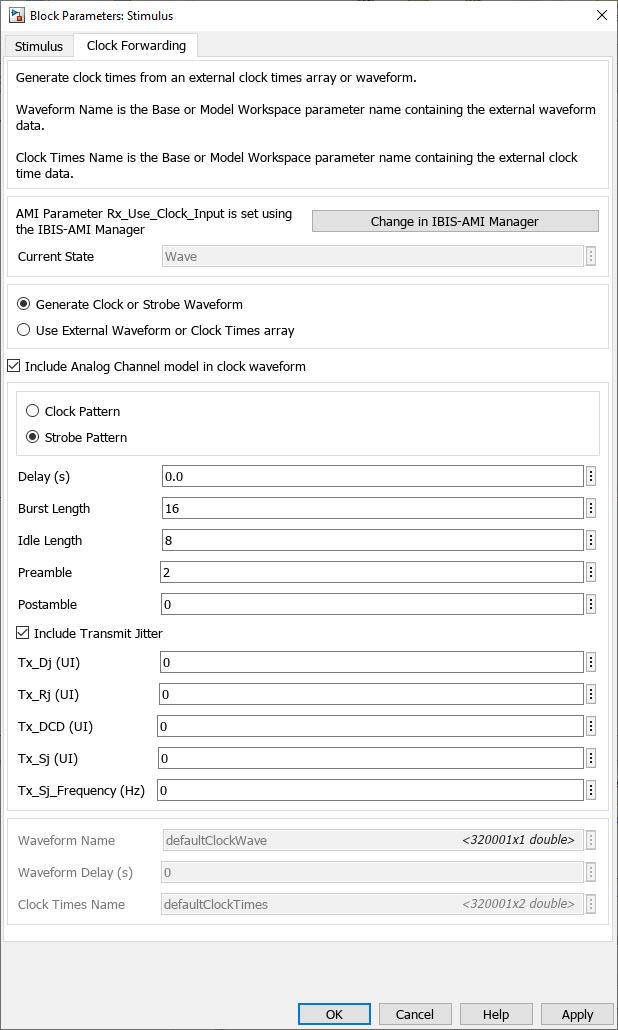
The SerDes toolbox Stimulus block is used to generate the stimulus for both the regular data path and the external clock or strobe. The regular data path uses the Stimulus tab while the external clock or strobe signal is generated with the Clock Forwarding tab.
When Rx_Use_Clock_Input is set to "None" in the IBIS-AMI Manager, the settings in this dialog box are ignored.
When Rx_Use_Clock_Input is set to "Times", this dialog box is used to set the name of the clock times array that resides in the Base Workspace or the Model Workspace. These times are used directly by the DFEClkFwd block. The array name is defined in the Clock Times Name field. For more information about generating this clock times array, see Creating a new clock times array.
When Rx_Use_Clock_Input is set to "Wave", this dialog box can generate a clock or strobe waveform, with or without jitter, and can be passed through the same analog channel model that the data path is using. It can also be used to set the name of a waveform array that reside in the Base Workspace or the Model Workspace. This waveform will be passed through a zero-crossing detector and the resulting clock times are used directly by the DFEClkFwd block.
To define a clock or strobe waveform, select the Generate Clock or Strobe Waveform radio button.
Select between a Clock Pattern (continuous 1010 pattern) or a Strobe Pattern (0101 pattern than can contain a "pause" or interspersed string of 0's) using the appropriate radio button.
Use the Include Transmit Jitter checkbox to enable Tx jitter in the stimulus pattern.
Delay defines the offset between the regular stimulus and the clock or strobe stimulus.
Burst Length defines the number of symbols in a strobe burst (clock pattern).
Idle Length defines the number of symbols between strobe bursts.
Preamble defines the number of additional clock cycles (two symbols) added to the beginning of each burst.
Postamble defines the number of additional clock cycles (two symbols) added to the end of each burst.
Tx_Dj defines the stimulus deterministic jitter.
Tx_Rj defines the stimulus random jitter.
Tx_DCD defines the stimulus duty cycle distortion.
Tx_Sj defines the stimulus sinusoidal jitter.
Tx_Sj_Frequency defines the frequency at which the stimulus sinusoidal jitter is defined.
To use the name of a clock or strobe waveform array from the Base Workspace or the Model Workspace, select the Use External Waveform or Clock Times array radio button and define the Waveform Name. For more information about defining this waveform array, see Creating a new clock or strobe waveform array.
When the Include Analog Channel model in clock waveform checkbox is selected, the resulting clock or strobe waveform will be fed through the same analog channel as the regular data path.
Note: An ideal clock waveform, defaultClockWave, and ideal clock times, defaultClockTimes, are automatically generated when clock-forwarding has been enabled. These arrays will be regenerated automatically whenever the Symbol time, Samples per symbol, or Number of symbols is changed. Any custom array that is pointed to by the model will need to be manually updated if any of these values change.
How to Visualize Results
To assist in debug or to verify proper operation of clock-forwarding, plotting the waveforms and/or clock-ticks can be very helpful. This is accomplished by using data logging to enable the use of the Data Inspector for plotting waveforms. The primary nodes of interest have already been logged for you, however you will need to enable data logging on the clock or strobe waveform manually:
Select the Stimulus block, then type Ctrl-U to look under the Stimulus block mask.
Double-click on the Clock Forward block to open the Clock Forward variant subsystem.
Right-click on the output of the Switch block and select
Log Signalfrom the Signal menu as shown below:

After running another simulation, the clock or strobe waveform will show up in the Data Inspector as Switch:1, the clock times into the Rx model are labeled Forward Clock Times:1, while the clock times out of the Rx model are labeled clockTime and the Rx model output waveform is labeled rxOut. To turn on additional data logging, repeat the above process by right-clicking on any signal and select Log Signals.
Plotting Clock and Data Waveforms
After running a simulation open the Data Inspector by clicking on the ![]() -icon in the Simulink Simulation tab. In the Data Inspector check the boxes for Switch:1 (the incoming clock or strobe waveform, Red in the figure below) and for rxOut (the Rx model out waveform, blue in the figure below). You should see that the rising/falling edges of the external clock or strobe waveform (Red) correspond with the rising/falling edges of the Rx model waveform (Blue). If they do not line up as expected, the offset can be adjusted by using the clock offset (see Setting the clock offset) or the stimulus Delay parameter (see Generating Clock and Strobe Waveforms).
-icon in the Simulink Simulation tab. In the Data Inspector check the boxes for Switch:1 (the incoming clock or strobe waveform, Red in the figure below) and for rxOut (the Rx model out waveform, blue in the figure below). You should see that the rising/falling edges of the external clock or strobe waveform (Red) correspond with the rising/falling edges of the Rx model waveform (Blue). If they do not line up as expected, the offset can be adjusted by using the clock offset (see Setting the clock offset) or the stimulus Delay parameter (see Generating Clock and Strobe Waveforms).
Plotting Clock-Ticks In and Out
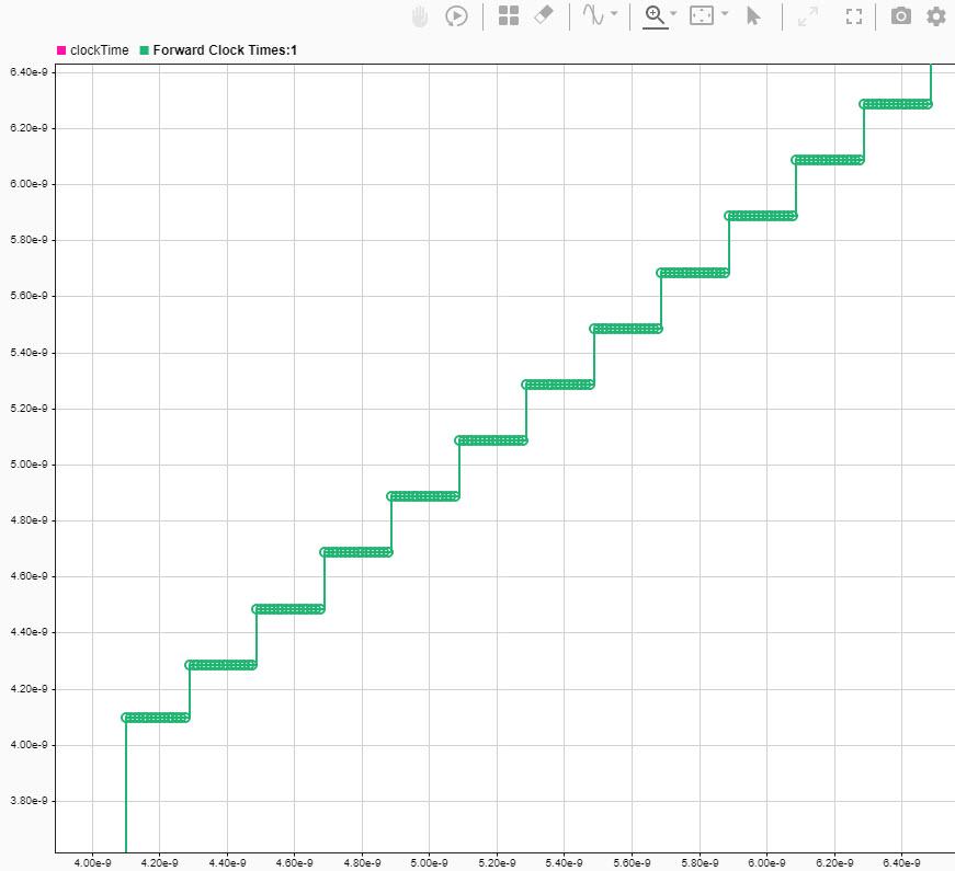
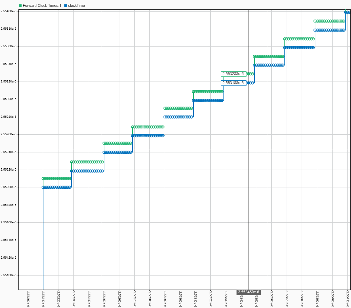
After running a simulation, in the Data Inspector check the boxes for Forward Clock Times:1 (the clock-times into the Rx model) and clockTime (the clock-times out of the Rx model). In the figure below, with Forward Clock Offset and the waveform Delay set to 0, the clock-times out of the Rx model (blue) trail the clock-times into the model (green) by 100ps (exactly UI/2). This is because the IBIS-AMI Specification states that the clock times output from the Rx AMI model must be exactly symbol_time/2 before the input data signal is sampled.
If the Forward Clock Offset was set to 8 samples (Samples Per Symbol / 2) then the clockTimes won't change, but they will occur 8 samples later.
If the Forward Clock Offset remained at 0, but instead the strobe waveform was delayed by 100ps (Symbol Time / 2) then the waveforms will look the same as the figure below, but both waveforms will be shifted in time by 100ps.
Creating New Clock or Strobe Waveform Array
Generating a new clock or strobe waveform for use in the clock-forwarding tab of the Stimulus block is accomplished using Parallel Link Designer (part of Signal Integrity Toolbox™), Signal Integrity Link and the MATLAB scripting interface to Signal Integrity Toolbox. Note that since you are only interested in creating a stimulus pattern, any AMI model can be used for this process. The following steps assume you are using the dq_clock_forward IBIS-AMI model generated at the end of this example.
Here is an overview of the required steps. For additional information on using Signal Integrity Link, see Signal Integrity Link. Note that if you have previously run Signal Integrity Link on this Simulink model you can begin with step 3.
Start by using the SerDes IBIS-AMI Manager to export the Tx and Rx models. Make sure that the IBIS file, AMI files and DLL files boxes are checked.
Use Signal Integrity Link to Create a new Parallel Link Designer project named
pld_stim_gen.In the new Parallel Link Designer project, double-click on the Tx designator then press the IO Stimulus button in the Designator Element Properties dialog box.
In the Stimuli dialog box, press the New button to open the Stimulus Editor and create the desired clock or strobe pattern. For example, you can set a continuous-clock pattern that repeats, or a burst-strobe pattern that starts and stops.
When you are done creating a new stimulus, make sure the new named stimulus pattern is selected in Designator Element Properties.
Use the Simulation Parameters dialog box to set the desired Samples Per Bit, Record Start and Record Bits values to capture the desired number of samples. For example, to record 16,000 samples, set Samples Per Bit to 16, Record Start to
0UI, and Record Bits to10,000UI, making sure that Time Domain Stop is >=10,000UI. Note: Number of samples = Samples Per Bit * Record Bits.Run the Parallel Link Designer simulation to generate the new Stimulus pattern.
Once simulations are complete, close Parallel Link Designer, then use the MATLAB scripting interface to Signal Integrity Toolbox to generate the stimulus waveform as follows in MATLAB:
% Create a SignalIntegrityProject object
% Note: Replace 'pld_stim_gen' with your Signal Integrity Toolbox project name
sip = SignalIntegrityProject('pld_stim_gen',opendesigner=false);

% Create a SignalIntegrityWaveform object
resultFiles = sip.Sheets.Simulations.Waveforms;

% Extract stimulus waveform from the TimeDomain waveform file
stimulus = resultFiles(9).table;

% Format stimulus waveform for use in SerDes Toolbox
stimWaveArray = stimulus{:,2};

% Center stimulus waveform around 0V
stimWaveArray = stimWaveArray - 0.5;

% Done
sip.exit
To use the new stimulus array, open the Clock Forwarding tab of the Stimulus dialog box, make sure the current state of Rx_Use_Clock_Input is set to Wave, select the radio button for Use External Waveform or Clock Times array, then enter the name of the new stimulus array (in this case: stimWaveArray) in the Waveform Name box.
Notes:
The Symbol time and Samples per symbol in Signal Integrity toolbox must match the values used in SerDes Toolbox.
If you change the Symbol time or Samples per symbol, you must regenerate the stimulus waveform array. The existing array will not be re-sampled.
Using the script above, the generated stimulus waveform array is placed in the MATLAB Workspace. You can copy this array into the Simulink model by opening the Model Explorer in Simulink and copying the array from the Base Workspace to the Model Workspace.
If you increase the Number of symbols to simulate in Simulink, you may need to increase Record Bits in Signal Integrity Toolbox accordingly.
Creating New Clock Times Array
Generating new clock ticks for use in the clock-forwarding tab of the Stimulus block is accomplished using Parallel Link Designer (part of Signal Integrity Toolbox), Signal Integrity Link and the MATLAB scripting interface to Signal Integrity Toolbox. Unlike with the new clock or strobe waveform array process above, here it is recommended to use the actual clock or strobe AMI model. The following steps assume you are using the dqs_clock_forward model included with this example. For more information on the Clock/Strobe model see Strobe Rx IBIS-AMI Model Requirements.
Here is an overview of the required steps. Note that if you have previously run Signal Integrity Link on the dqs_clock_forward Simulink model you can begin with step 3.
Start by using the SerDes IBIS-AMI Manager to export the Tx and Rx models. Make sure that the IBIS file, AMI files and DLL files boxes are checked.
Use Signal Integrity Link to Create a new Parallel Link Designer project named
pld_clock_gen.In the new Parallel Link Designer project open the Simulation Parameters dialog box and set the parameter Output Clock Ticks to Yes.
Use the Simulation Parameters dialog box to set the desired Samples Per Bit, Record Start and Record Bits values to capture the desired number of samples. For example, to record 10,000 UI, set Samples Per Bit to 16, Record Start to
0UI, and Record Bits to10,000UI, making sure that Time Domain Stop is >=10,000UI. Note: Number of samples = Samples Per Bit * Record Bits.<Optional>: While you can run the simulation using the default setup from Signal Integrity Link, it is recommended that you set up a widebus simulation with a realistic topology that includes both the
dq_clock_forwardand thedqs_clock_forwardmodels.Run the desired Parallel Link Designer simulation.
Once simulations are complete, close Parallel Link Designer, then use the MATLAB scripting interface to Signal Integrity Toolbox to generate the new clock times array as follows in MATLAB:
% Create a SignalIntegrityProject object
% Note: Replace 'pld_clock_gen' with your Signal Integrity Toolbox project name
sip = SignalIntegrityProject('pld_clock_gen',opendesigner=false);

% Create a SignalIntegrityWaveform object
resultFiles = sip.Sheets.Simulations.Waveforms;

% Extract clock times from the TimeDomain clock_ticks file
clockTimes = resultFiles(10).table;

% Format clock times for use in SerDes Toolbox
clockTimesArray = clockTimes{:,1:2};

% Done
sip.exit
To use the new clock times array, open the Clock Forwarding tab of the Stimulus dialog box, make sure the current state of Rx_Use_Clock_Input is set to Times, select the radio button for Use External Waveform or Clock Times array, then enter the name of the new stimulus array (in this case: clockTimesArray) in the Clock Times Name box.
Notes:
Ignore Bits has no affect on clock times out.
Record Start and Record Bits do affect clock times out.
Since clock times are only output every transition, depending on the stimulus pattern used you may need to make the value of Record Bits much larger to capture the appropriate number of UI.
Make sure to point the Clock/Strobe designator name and not the Data designator name.
Generate Rx IBIS-AMI Model
The final part of this example takes the customized Simulink model and generates IBIS-AMI compliant model executables, IBIS and AMI files for the clock-forwarding receiver.
Open the Block Parameter dialog box for the Configuration block and click on the Open SerDes IBIS-AMI Manager button.
On the AMI-Rx tab in the SerDes IBIS-AMI Manager, make sure that the current value of all parameters are set to the appropriate values since they may have been modified while working through this example:
Rx_Use_Clock_Input should be set to
None.ForwardClockOffset should be set to
0.Mode should be set to
Fixed.All TapWeights should be set to
0.
Export Models
On the Export tab in the SerDes IBIS-AMI manager:
Update the Tx model name to
ddr_tx.Update the Rx model name to
clock_forward_dq_rx.Note that the Tx and Rx corner percentage is set to
10. This will scale the min/max analog model corner values by +/-10%.Verify that Dual model is selected for the Rx AMI Model Settings. This will create a model executable that support both statistical (Init) and time domain (GetWave) analysis.
Set the Tx model Bits to ignore value to
10to allow bits to propagate through the FFE.Set the Rx model Bits to ignore value to
1000to allow enough time for the external clock waveform to settle during time domain simulations.Set Models to export to Both Tx and Rx.
Set the IBIS file name to be
clock_forwarding.ibsPress the Export button to generate models in the Target directory.
Review AMI File
The resulting Rx AMI file will look like a normal Rx AMI file with two exceptions. First, the AMI_Version is set to 7.1, while the second is the inclusion of the reserved parameter Rx_Use_Clock_Input.
Tips
With clock forwarding, any data transition that does not have an associated clock time will be ignored. For example, when using a strobe stimulus pattern, if a data transition occurs during the strobe idle period, this transition will be lost.
When using the Delay option in the stimulus or the AMI parameter ForwardClockOffset to align the clock signal with the data signal as desired, note that the inclusion of DFE in the data path can increase the edge-rate of the data signal such that the equalized waveform can cross Vref well before the un-equalized clock waveform. This can result in an apparent timing offset between data and clock as more DFE is applied, which means the clock signal may not necessarily need to offset by a full 90 degrees.
The Tx FFE block introduces a 1UI delay for every pre-tap present. If there is no FFE in the clock or strobe Tx AMI model (such as the dqs_clock_forward.slx model described below), this can cause a 1UI+ difference in the time between when the stimulus is applied and when the signal reaches the Rx data decision point. The delay will need to be accounted for when including the affects of correlated vs un-correlated jitter.
When using the zero-crossing detector to generate clock times (such as in the dqs_clock_forward.slx model described below), generally the results with Rx_Use_Clock_Input set to "Wave" will be the same as when set to "Times". However, if a conventional CDR is used to generate clock times, the resulting clock times will be output starting at time = ~0. In this case, the results with Rx_Use_Clock_Input set to "Wave" will not be equivalent to when it set to "Times".
Model Limitations
This clock forwarding AMI model requires an EDA tool that supports the IBIS 7.1 reserved parameter Rx_Use_Clock_Input.
Per the IBIS 7.1 specification, it is intended that Data and Strobe AMI models will be delivered as a matched pair. This may place additional requirements on the Strobe AMI model which are discussed in the next section.
Strobe Rx IBIS-AMI Model Requirements
Per the IBIS 7.1 specification, it is intended that Data and Strobe AMI models will be delivered as a matched pair. This means that a Strobe (or Clock) AMI model will also need to be generated for use along with this Data AMI model. The Strobe model should not use a CDR to generate clock times, but instead should only output clock times at the zero-crossings of the output waveform, which can be handled by using a MATLAB Function Block. Additional features for the Strobe AMI model include the handling of strobe pre-amble (only output clock times after the end of the pre-amble) and handling of Single-Data-Rate (SDR) signals such as a Clock that only outputs clock times on the rising edge of the output waveform.
An example Strobe/Clock AMI model is attached to this example and can be opened by typing the following command:
>> open_system('dqs_clock_forward.slx')
This model contains a pass-through differential Tx and Rx. The Rx AMI model outputs clock times only at zero-crossings and contains two controls:
DQS_Preamble: The number of DQS transitions to skip before outputting clock times during a DQS burst. Currently requires at least 4 DQS UI between bursts. (1tCK = 2 DQS UI). The Default value is "2tCK". When using this Rx as a Clock receiver, this value should be set to "0tCK".
Strobe_or_Clock: Switch between a Strobe or Clock signal. A Strobe signal returns clock times every edge (DDR) while a Clock signal only returns clock times on rising edges (SDR). The Default is "Strobe".
Test Generated IBIS-AMI Models
The clock forwarding receiver IBIS-AMI model is now complete and ready to be tested in any industry standard AMI model simulator that supports IBIS 7.1.
References
See Also
Topics
- DDR5 IBIS-AMI with Clock Forwarding (Signal Integrity Toolbox)
- LPDDR5X IBIS-AMI Models with Clock Forwarding