GPS and How It Works
This topic provides a foundational understanding of the Global Positioning System (GPS), its segment structure, signal specifications of both legacy and modernized signals, and the accuracy GPS provides. This topic also explains in detail how the trilateration technique underlies the functioning of GPS.
The GPS is a space-based radio-navigation infrastructure that consists of a constellation of satellites that broadcast navigation signals, and a network of ground stations and satellite control stations to monitor and control these satellites. Multiple GPS navigation satellites have been launched to date, and these satellites are typically classified in blocks. There are multiple satellite blocks, which host several satellites. By the end of 2023, the launched blocks include Block Ⅰ, Ⅱ, ⅡA, ⅡR, ⅡRM, ⅡF, Ⅲ, and ⅢF. These blocks contain different generations of GPS satellites with differing capabilities.
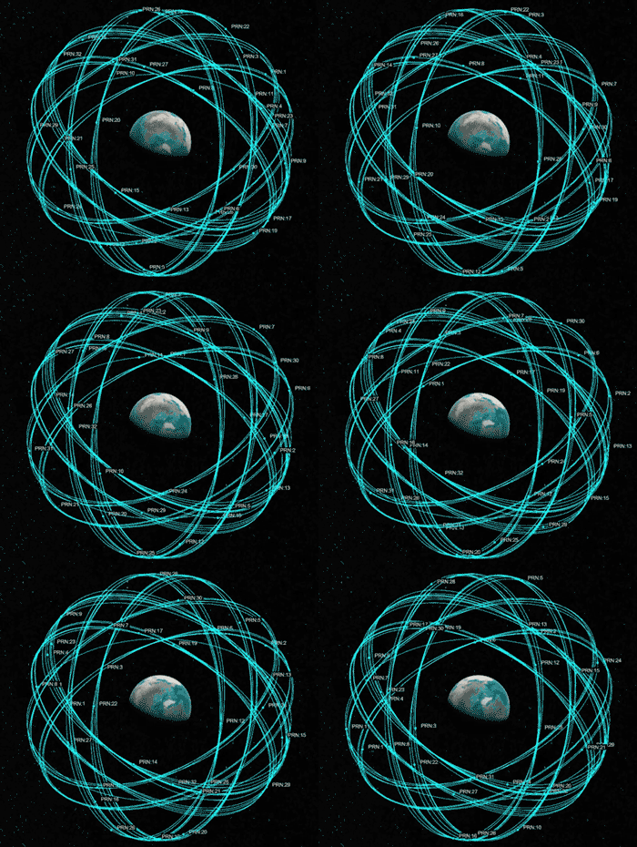
Thirty-one GPS satellites are in the 24-slot constellation, strategically positioned in one of six orbital planes surrounding the Earth at an altitude of approximately 20,200 km. The 24-slot formation ensures that a minimum of four satellites are in line of sight from any location on the Earth's surface. The remaining satellites uphold continuous coverage and operational integrity during periods when primary satellites undergo maintenance, or are phased out of service, and enhance the overall performance of the GPS. Originally developed by the United States Department of Defense for military applications, the GPS has been extended for civilian usage, achieving full operational capability in the year 1993.
These summarize the essential elements of the GPS signal:
GPS satellites use three distinct frequencies for civilian applications — L1 at 1575.42 MHz, L2 at 1227.60 MHz, and L5 at 1176.45 MHz.
The satellite network uses a code-division multiple access (CDMA) spread-spectrum method. In this approach, message data transmitted at a low bit rate is encoded with a high-rate pseudo-random number (PRN) sequence to achieve a unique PRN ID for each satellite.
GPS uses five distinct civilian signals — coarse acquisition (C/A) code and precision (P) code in the legacy L1 band, modernized L1 civil (L1C) code in the L1 band, civil-moderate (CM) code and the civil-long length (CL) code in the L2C band, and in-phase code (I5-code) and quadrature-phase code (Q5-code) in the L5 band.
This table describes the frequency each GPS band uses.
Band | Frequency | Description |
---|---|---|
L1 | 1575.42 MHz | C/A, P, L1 civil (L1C), and military (M) codes |
L2 | 1227.60 MHz | P, L2C, and M-code |
L3 | 1381.05 MHz | Used for nuclear detonation detection |
L4 | 1379.91 MHz | Studied for ionospheric corrections |
L5 | 1176.45 MHz | Support applications critical to civilian safety-of-life (SoL) |
GPS Segments
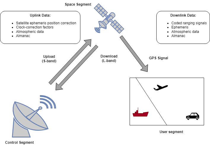
GPS consists of three segments: the control segment, the space segment, and the user segment. Together, these provide location information.
Control segment — The control segment consists of a network of tracking stations, master control stations, and ground antennas. Operational responsibilities encompass the monitoring of GPS satellites to ascertain and forecast their positions, evaluate system integrity, assess the performance of the onboard atomic clocks, gather atmospheric data, update the satellite almanac, and address additional relevant factors. The control segment then compiles and transmits this data to the GPS satellites using an S-band link. Monitoring facilities are strategically positioned across the globe, spanning North and South America, Africa, Europe, Asia, and Australia.
Space segment — The space segment consists of satellites in orbit around the Earth, which are responsible for transmitting signals that provide users with data regarding their geographical position and the time of day. The primary functions of these satellites include the reception and storage of data provided by the control segment. These satellites maintain precise timekeeping by using onboard atomic clocks, and disseminate information and signals to users through three L-band frequencies (L1, L2, and L5).
User segment — The user segment encompasses devices equipped with GPS receiving capabilities, such as wristwatches and mobile phones. These GPS receivers are engineered to transform signals from satellites into precise estimations of position, speed, and temporal data.
How GPS Works
GPS operation is based on the principles of ranging and trilateration, utilizing a constellation of satellites as exact points of reference.
GPS and other global navigation satellite system (GNSS) signals follow the same principles of ranging and trilateration to determine the receiver position.
The first time a GPS receiver is turned on, it downloads orbital information from the visible satellites (ephemeris), which can take up to a minute. However, it takes 12.5 minutes to download the orbital information of all the satellites (almanac). To determine a receiver position anywhere on the Earth, you must have a combination of signals emitted from a minimum of four satellites. GPS satellites have atomic clocks that provide extremely accurate time. Satellite signals contain the time information so that a receiver can continuously determine the time a signal was broadcast. A receiver uses this signal data and the time difference between the time of signal reception and the broadcast time to calculate its distance from the satellites.
Each satellite continuously broadcasts a navigation message that contains this information:
Ephemeris — Provides details about the position of individual satellites at a reference time. The satellite uses an orbit propagator to determine the position of the satellite at any time instance of the signal transmission.
Time — The GPS system time, derived from an atomic clock integrated into the satellite.
Almanac — Contains coarse orbit information and orbital data pertaining to each satellite in the entire constellation.
GPS receivers acquire these transmissions and match the received code with a reference code, using the precise time of arrival to determine the spatial separation between the device and the orbiting satellite. This generic equation calculates the distance between the transmitter and receiver.
Distance = Speed of light × (time at which signal is received – time at which signal was transmitted)
Receiver Position in 2-D Plane
Utilizing trilateration, the GPS receiver accurately determines its location by employing the computed pseudo-distances in conjunction with positional data provided by the satellites. To understand trilateration, first consider a position fix in a 2-D plane.
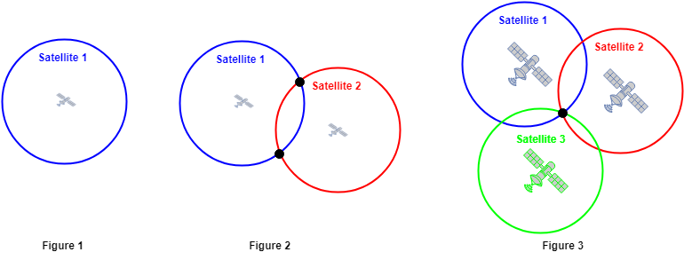
The distance from a satellite to the receiver points to several locations on the Earth that form a circle, with the distance between the satellite and the receiver as its radius. This results in a situation where the position of the receiver can be anywhere on the circumference of this circle, as shown in Figure 1.
The distance of the receiver from two satellites in the constellation reduces the possible location of the receiver to the points where the distance arcs of the two circles intersect, resulting in two points of intersection, as shown in Figure 2.
The distance of the receiver with respect to a third satellite helps correctly identifying the receiver coordinates, removing the ambiguity and providing the exact location in the X-Y plane, as shown in Figure 3. This process is also known as the 2-D fix or 2-D trilateration, because the points of intersection are all located on a two-dimensional plane. With the addition of altitude, 3-D trilateration comes into play.
Receiver Position in 3-D Plane
Since the real world is a three-dimensional space, 3-D position of the GPS receiver is required, that is, its latitude, longitude, and altitude.
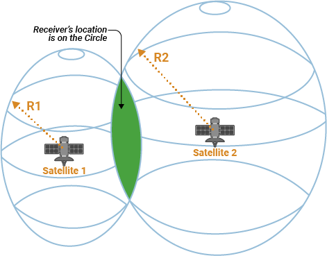
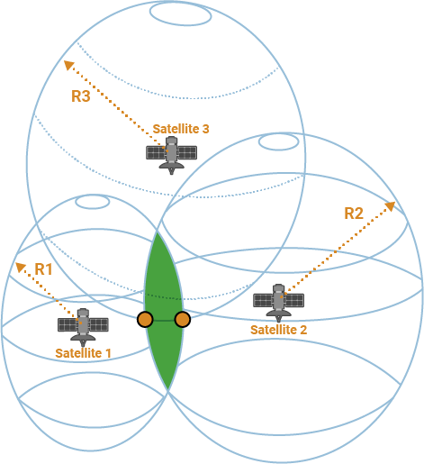
In 3-D, each satellite is actually in the center of a sphere rather than a circle.
With two satellites, you can limit the position of the receiver to the circle formed by the intersection of the two spheres with radii R1 and R2 , representing the distance of satellites 1 and 2 from the receiver, respectively.
With the addition of the third satellite, you can narrow down the position of the GPS receiver to the intersection of three spheres, that is, two points.
Practically, one of these points is not viable, as it is too far off in space to be the GPS receiver location. Thus, the information about the distances of these three satellites from the receiver and the locations of the satellites when the signal was sent is sufficient to determine the receiver position in 3-D (latitude, longitude, and altitude). You must use an atomic clock synchronized to GPS to compute the ranges from these three satellite signals, but, because atomic clock in GPS receivers is not practical, receiver time bias is still a factor left in estimating the receiver position. However, by taking a measurement from a fourth satellite, the receiver avoids the atomic clock requirement. Thus, by using four satellites, a receiver can compute its latitude, longitude, altitude, and precise receiver time.
GPS Signals
There are four GPS signal specifications designed for civilian use. In order of date of introduction, these are L1 C/A, L2C, L5, and L1C. L1 C/A is also called the legacy signal, and L2C, L5, and L1C are modernized signals. The GPS satellites simultaneously transmit several ranging codes and navigation data. All GPS satellites broadcast at the same frequencies and use different ranging codes so receivers can distinguish individual satellites from each other using CDMA.
Legacy GPS signals
The original GPS design uses two frequencies: L1 at 1575.42 MHz (10.23 MHz × 154), and L2 at 1227.60 MHz (10.23 MHz × 120).
Legacy GPS design contains these ranging codes:
C/A-code — This ranging code uses the BPSK modulation technique to transmit on the L1 frequency. It consists of a 1023-bit sequence that repeats every millisecond. For more information, see
gnssCACode
.This code is available for civilian use without any restrictions.
P-code — This ranging code also uses the BPSK modulation technique to transmit on the L1 and L2 frequencies at a chip rate of 10.23 Mcps. The higher chip rate in P-code contributes to an increase in accuracy when compared to C/A-code. For more information, see
gpsPCode
.
The legacy navigation message (LNAV) is transmitted in 1500 bit-length frames, with each frame consisting of five subframes of 300 bits each. Because the data rate is 50 bps, transmitting each subframe takes 6 seconds, and transmitting each frame takes 30 seconds. Each subframe consists of 10 words with 30 bits (24 data bits and 6 parity bits) in each word. The GPS data contains information regarding the clock and the position of the satellites. This figure shows the frame structure of the LNAV data.
For more details, see the GPS Waveform Generation example.
This table describes the content of each LNAV message subframe.
Subframe Word Description 1 1–2 Telemetry word (TLM) and handover word (HOW) 3–10 Satellite clock and GPS time relationship 2–3 1–2 TLM and HOW 3–10 Ephemeris 4–5 1–2 TLM and HOW 3–10 Almanac, ionospheric, and UTC data
Modernized GPS signals
Modernized GPS civilian signals are characterized by two primary advancements: incorporation of a dataless acquisition aid and application of forward error correction (FEC) coding to the navigation message. The dataless acquisition aid is an additional signal transmitted concurrently with the data signal to facilitate the acquisition of the GPS signal and to improve the power levels. Navigation data has a slow transmission rate, typically at 50 bits per second, and minor disruptions yield disproportionately significant consequences. Hence, implementation of the FEC coding to the navigation message significantly enhances the resilience of the modernized GPS signals.
To increase the quality of service (QoS), modernized GPS introduces these new signals.
L1C — This signal is open for civilian use and broadcasts on the L1 frequency. It uses the binary offset carrier (BOC) modulation scheme. For details on BOC modulation, see
bocmod
.L1C consists of two ranging code components, pilot and data ranging codes, and an overlay code component. The PRN codes are 10,230 chips long and transmitted at 1.023 Mcps, thus repeating every 10 ms. For more information, see
gpsL1CCodes
.L2C — This signal is also open for civilian use and broadcasts on the L2 frequency. Unlike the C/A-code, L2C contains two unique PRN code sequences to provide ranging information, the CM code and the CL code. These codes are designed to deliver precise ranging information. The CM code is 10,230 chips long and repeats every 20 ms. The CL code is 767,250 chips long and repeats every 1,500 ms. Each signal is transmitted at 511,500 chips per second. However, the signal multiplexes CM and CL together to form a 1.023 Mcps signal.
M-code — This signal is restricted for military use and is designed to further improve the anti-jamming and secure access of military GPS signals. M-code broadcasts on both the L1 and L2 frequencies. The signal has distinct sideband lobes to improve the signal reception.
L5 — This signal is open for civilian use and broadcasts at the L5 frequency. L5 is designed to meet demanding requirements for SoL transportation and other high-performance applications. L5 supports an advanced signal structure that delivers superior performance with a higher transmission power relative to the L1 and L2 signals. This enhancement equates to approximately 3 dB, or a twofold increase in power. An L5 signal transmit two PRN ranging codes, in-phase code (I5-code) and quadrature-phase code (Q5-code). Both codes are 10,230 chips long, transmit at 10.23 Mcps, and repeat after 1 ms. Generation of I5-code and Q5-code is identical, differing only in initial state. For more information, see
gpsL5Codes
.
Modernized signals use an enhanced version of the original LNAV message: civil navigation (CNAV) message. CNAV data is more accurate and has higher precision representation. L2C and L5 use the CNAV message structure, whereas L1C uses a different message structure called CNAV-2.
L2C and L5 — The CNAV data transmits continuously in the form of message types. Each message type consists of 300 bits, transmitted at 25 bps for L2C and 50 bps for L5. These bits pass through a rate-half convolutional-encoder to obtain 600 bits from each message type at 50 bps for L2C and 100 bps for L5. Transmitting each message type takes 12 seconds for L2C and 6 seconds for L5. The order in which each message type is transmits is completely arbitrary, but is sequenced to provide the optimal user experience. This figure shows the CNAV message structure for L2C. The L5 CNAV message structure is similar to L2C, but it sends data twice as fast at each step.
This table describes the content of each CNAV message bit.
Bits Description 1–8 Preamble 9–14 PRN of transmitting satellite 15–20 Message type ID 21–37 Truncated time of week (TOW) count 38 Alert flag 39–276 Navigation message payload 277–300 Cyclic redundancy check L1C — The data rate of CNAV-2 data is 100 bps. Each frame of CNAV-2 data consists of 1800 bits, which is further divided into three subframes. The frames of L1C are similar to the messages of L2C CNAV and L5 CNAV. L2C CNAV and L5 CNAV use a dedicated message type for ephemeris, while all CNAV-2 frames include that information. This figure shows the CNAV-2 message structure.
This table describes the content of each CNAV-2 message subframe.
Subframe Bit Count Description Raw Encoded 1 9 52 Time of interval (TOI) 2 600 1200 Time correction and ephemeris data 3 274 548 Variable data (almanac, ionospheric information, UTC)
GPS Accuracy
For the positional precision of the satellites, the GPS control segment perpetually surveils the precise spatial coordinates (ephemeris) and chronometric parameters of each satellite to uphold the integrity of system accuracy. The ephemeris data is accurate to within 2 meters, and often even better. GPS-enabled smartphones are typically accurate to within 4.9 m (16 ft), which you can improve to centimeter level by using dual-frequency receivers and augmentation systems. The accuracy of GPS varies depending on several factors, including the type of GPS receiver, the environment, the quality of the satellite signals, and the current satellite geometry in the sky.