Stepped Impedance Maximally Flat Lowpass Filter for Microwave Applications
This example shows you how to design a stepped-impedance lowpass filter for X-band applications.
Microstrip filter plays an important role in microwave applications. Almost all communication systems contain an RF front end which performs signal processing using RF filters. Microwave lowpass filters attenuate the unwanted signals above the cutoff frequency. These filters have very low insertion loss and are easy to fabricate in compact sizes.
The stepped impedance low-pass microstrip filters is a cascaded structure of alternating high and low impedance transmission lines. These lines act as semi lumped elements as they are much shorter than the associated guided wavelength. The high-impedance lines act as series inductors and the low-impedance lines act as shunt capacitors. Therefore, this filter structure is directly realizing the L-C ladder type (LC-Pi) of low-pass filters.
Here the stepped impedance low-pass filter and the lumped element model is analyzed for a cut off frequency of 9 GHz. The results of lumped element model and the simulation model are compared and validated [1].
Design Stepped Impedance Low-Pass Filter
Design a stepped impedance low-pass filter at 9 GHz on an aluminium substrate and visualize it.
freq = 9e9;
sub  = dielectric("Name",{'Fr4'},"EpsilonR",9.6,"LossTangent",0,"Thickness",1.6e-3);
obj  = filterStepImpedanceLowPass;
obj.FilterOrder = 7;
obj.Substrate = sub;
d   = design(obj,freq,'Z0',50,'HighZ',120,'LowZ',20);
figure; show(d);

Analyze Using Lumped Element Model
The figure shows the schematic of lumped element model for a 7th order low-pass LC-Pi configuration.
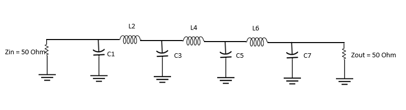
Model the 7th order maximally flat low-pass filter at 9 GHz using the rffilter object from RF Toolbox. Analyze its s-parameter behavior with input and output impedance at 50 ohm.
Lpfilter = rffilter('FilterType','Butterworth','ResponseType','LowPass', ...
                'Implementation','LC pi','FilterOrder',obj.FilterOrder,'PassbandFrequency',freq,...
                'PassbandAttenuation',3.0103,'Zin',50,'Zout',50,'Name','Filter');
spar = sparameters(Lpfilter,linspace(0.1e9,12e9,51));
figure; rfplot(spar);

It is clear from the scattering parameters that the cut-off frequency is at 9 GHz and the stop band attenuation is more than 20dB using the lumped element model.
Analyze Using Simulation Model
Analyze the simulation model for its s-parameter behavior at 50 ohm reference impedance.
s11 = sparameters(d,linspace(0.1e9,12e9,51));
figure; rfplot(s11)
ylim([-50,0]);

The scattering parameters obtained from the filter layout realization using simulation model are more accurate because the coupling effect between microstrip line sections are considered along with the losses. The s-parameters plot shows that the cut-off frequency is reduced to 5.8 GHz. This reduction is due to two reasons. One is the coupling effect between each section and the second is the design method for modeling the filter which uses the analytical equations where those effects are not considered. Hence, the design will give approximate results, and you should optimize the length and width of the High and Low impedance lines to shift the cut-off frequency to the desired value.
Use the current function to plot the current distribution on the surface of the stepped impedance low-pass filter below the cut off frequency and view its mesh.
figure;
current(d,3e9,'scale','log10');

figure;
mesh(d);

Designing the stepped impedance low-pass filter at S-band and below will exhibit less shift in frequency nearly about 0.5 GHz when compared with the shift in design at high frequencies.
Conclusion
The stepped impedance low-pass filter is designed and analyzed using the design function at 9 GHz cut off frequency. The design is compared with both lumped model and the simulation model to understand the difference in shift in the frequency. It is seen that the shift in the frequency for simulation model is about 2.9 GHz which is due to the coupling effect. Hence, the design parameters of the stepped impedance low-pass filter should be optimized to achieve the desired cut-off frequency.
Reference
1. Salama,Y Battah,A Abuelhaija, 'Stepped Impedance 7th order Maximally Flat Low-Pass Filter Using Microstrip Line for X-Band Applications', Journal of Physics: Conference Series (ICERIA ).
2. Sheetal.Mitra, 'Stepped Impedance Microstrip Low-Pass Filter Implementation for S-band Application', International Journal of Latest Trends in Engineering and Technology (IJLTET), Vol. 5, Issue 3, May 2015.