Miniaturization and Bandstop region improvement of stub filter using Double Spurline
This example shows how to introduce a double spurline into a conventional open stub filter for filter circuit size miniaturization and bandstop region improvement using RF PCB Toolbox.
Bandstop filters are important devices in rejecting higher harmonics and spurious response for microwave, millimeter wave, and Terahertz applications. An open stub filter is a conventional filter, which is widely used for bandstop response. By cascading several open stubs in an open stub filter, a wider rejection bandwidth and a deeper rejection can be obtained at the expense of increasing the insertion loss in the passband and the overall circuit size. Using a double spurline of proper length inserted between double open stubs, a wider bandwidth and deeper rejection level is attained from the proposed filter without increasing the circuit size.
In this example, the section 1 shows the analysis of an open stub filter, section 2 shows the analysis of the double spurline, and section 3 shows the comparison of a conventional open stub filter and the open stub filter with double spurline.
Conventional Open stub filter
Create a conventional open stub filter using filterStub designed at 3.8 Ghz with the designed dimension given in [1].
stub = filterStub;
stub.StubDirection = [1 1];
stub.StubLength = [14.5e-3, 14.5e-3];
stub.StubWidth = [2.1e-3, 2.1e-3];
stub.SeriesLineLength = 15e-3+2.1e-3;
stub.SeriesLineWidth = 2.1e-3;
stub.PortLineLength = 6.45e-3;
stub.PortLineWidth = 2.1e-3;
stub.StubOffsetX = [-0.0085 0.00855];
sub = dielectric('Name',{'AD260A'},'EpsilonR',2.6,'LossTangent',0.001,'Thickness',0.76e-3);
stub.Substrate = sub;
stub.Height = 0.76e-3;
stub.GroundPlaneWidth = 30e-3;
figure; show(stub);
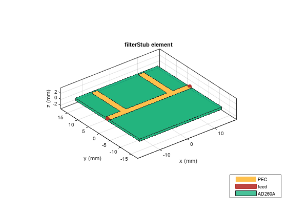
Note: The StubLength property is sensitive to frequency. The increase in stub length (achieved by using the StubLength property) will decrease the resonant frequency to the lower side.
Double spurline filter
Create a double spurline filer designed at 3.8 Ghz with the design dimensions given in [1]. Use the same dimension of the stub to create the spurline filter. Optimize the parameters such as CoupledLineWidth, CoupledLineSpacing, and LineGap to maintain the resonant frequency of spurline filter around 3.8 GHz
spurline = filterSpurline;
linegap = 0.4e-3;
clineS  = 0.4e-3;
clineW  = 0.4e-3;
spurline.CoupledLineSpacing = clineS;
spurline.CoupledLineWidth = clineW;
spurline.LineGap = linegap;
spurline.CoupledLineLength = stub.SeriesLineLength-stub.StubWidth(1,1)-linegap;
spurline.PortLineLength = stub.PortLineLength+stub.StubWidth(1,1)/2;
spurline.PortLineWidth = stub.PortLineWidth;
spurline.LineType = 'Double';
figure; show(spurline);
Comparison of conventional open stub filter and open stub filter with double spurline
To introduce the double spurline in the open stub filer, convert the stub filter into a pcbComponent.
ConventionalStub = pcbComponent(stub);
Get the shapes of the designed stub and the double spurline using the shapes method. The shapes method will have all the metal layers in the component. Layer 1 is the shape of the filter and Layer 2 is the ground.
Using the filter shapes, create the shape of open stub with double spurline.
shape1 = shapes(spurline).Layer1;
shape2 = shapes(stub).Layer1;
Len = stub.SeriesLineLength+ (2*stub.PortLineLength);
Wid = stub.PortLineWidth;
shape3 = traceRectangular('Length',30e-3,'Width',2.1e-3);
pcbShape = (shape2-shape3)+shape1;
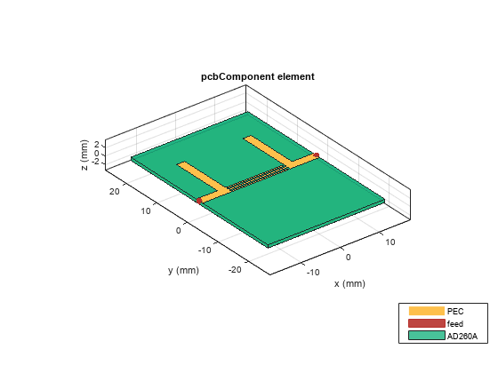
Create the component of the pcbShape (open stub with double spurline) using pcbComponent.
ProposedStub = pcbComponent;
ProposedStub.BoardThickness = 0.76e-3;
gnd = traceRectangular('Length',stub.GroundPlaneLength,'Width',1.5*stub.GroundPlaneWidth);
ProposedStub.BoardShape = gnd;
ProposedStub.Layers = {pcbShape,sub,gnd};
ProposedStub.FeedDiameter = stub.PortLineWidth/2;
ProposedStub.FeedLocations = [-stub.GroundPlaneLength/2,0,1,3;stub.GroundPlaneLength/2,0,1,3];
figure; show(ProposedStub);
Analyze the sparameter of the conventional stub and compare the characteristics with the proposed stub. Use a frequencySweep to set up a gradient-based adaptive interpolating sweep to calculate the s-parameters over a finely sampled frequency range of 1- 7 GHz. Adjust the default ErrTol and lower it to -100 and increase the maximum number of iterations for convergence to 40.
fsweep1 = frequencySweep;
fsweep1.SweepType = 'interpWithGrad';
fsweep1.ErrTol = -100;
fsweep1.NumIters = 40;
sparam_Conv = sparameters(ConventionalStub,linspace(1e9,7e9,300),'SweepOption',fsweep1); %sparameters(ConventionalStub,linspace(1e9,7e9,71));
figure; rfplot(sparam_Conv ,1,2);
fsweep2 = frequencySweep;
fsweep2.SweepType = 'interpWithGrad';
fsweep2.ErrTol = -100;
fsweep2.NumIters = 40;
sparam_Prop = sparameters(ProposedStub,linspace(1e9,7e9,300),'SweepOption',fsweep2); %sparameters(ProposedStub,linspace(1e9,7e9,71));
hold on; rfplot(sparam_Prop ,1,2);
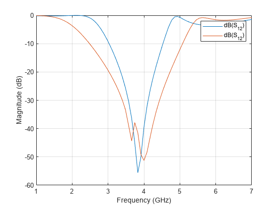
It is observed that the conventional stub exhibits the bandwidth of 3 to 4.5 GHz centered around 3.8 GHz and the stub with double spurline exhibits the bandwidth of 2.5 GHz to 5.11 GHz. Introducing the double spurline on the conventional stub obtains the deeper and wider rejection bandwidth without increasing the circuit size.
Reference
Niwat ANGKAWISITTPAN "Miniaturization of bandstop filter using double spurlines and double stubs ," PRZEGLĄD ELEKTROTECHNICZNY (Electrical Review), ISSN 0033-2097, R. 88 NR 11a/2012.