정상 상태 실험을 사용한 원심 펌프의 결함 진단
이 예제에서는 모델 기반 접근 방식을 사용하여 펌핑 시스템에서 발생하는 여러 유형의 결함을 검출하고 진단하는 방법을 보여줍니다. 이 예제는 Rolf Isermann의 저서 Fault Diagnosis Applications에서 제시하는 원심 펌프 분석을 따릅니다 [1].
펌프 감독 및 결함 검출
펌프는 전력, 화학, 광물, 광업, 제조, 난방, 냉방, 냉각과 같은 여러 산업 분야에서 꼭 필요한 장비입니다. 원심 펌프는 회전 운동 에너지를 유체 흐름의 유체 역학 에너지로 변환하여 유체를 이송하는 데 사용됩니다. 회전 에너지는 일반적으로 연소 기관 또는 전기 모터에서 발생합니다. 유체가 회전축을 따라 또는 회전축 부근에서 펌프 임펠러에 유입되면 임펠러에 의해 가속되어 방사형으로 확산 펌프를 향해 흐릅니다.
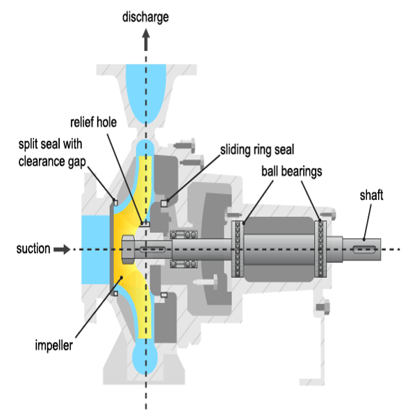
펌프는 유압 컴포넌트 또는 기계 컴포넌트에서 손상이 발생합니다. 가장 흔히 결함이 발생하는 컴포넌트는 슬라이딩 링 실과 볼 베어링이며, 구동 모터, 임펠러 블레이드, 슬라이딩 베어링과 같은 컴포넌트에서도 심심치 않게 고장이 발생합니다. 다음 표에는 가장 흔히 발생하는 유형의 결함이 나와 있습니다.
공동 현상: 정압이 증기압 미만으로 떨어질 경우 유체 내부의 증기포가 발생하는 현상입니다. 증기포가 급격히 붕괴하면서 블레이드 휠이 손상됩니다.
유체 내부의 기체: 압력이 떨어지면 유체 내부에 용존 기체가 발생합니다. 기체와 액체가 분리되고 헤드가 낮아집니다.
드라이 런: 유체가 없으면 냉각이 결여되고 베어링이 과열됩니다. 시작 단계에 중요합니다.
침식: 경질 입자나 공동 현상으로 인해 벽에 기계적 손상이 발생합니다.
부식: 침식성 유체로 인한 손상입니다.
베어링 마모: 피로 및 금속 마찰로 인한 기계적 손상으로 부식과 마손이 생성됩니다.
안전 천공 끼우기: 축방향 베어링의 과부하/손상이 발생합니다.
슬라이딩 링 실 끼우기: 마찰이 늘어나고 효율이 줄어듭니다.
분할 실 증가: 효율이 줄어듭니다.
침전: 유기 물질의 침전이나 회전 날개 입구 또는 출구에서의 화학 반응을 통한 침전은 효율을 낮추고 온도를 높입니다.
진동: 회전 날개의 손상 또는 침전으로 인한 회전 날개 불균형입니다. 베어링 손상을 일으킬 수 있습니다.
사용 가능한 센서
일반적으로 다음과 같은 신호가 측정됩니다.
주입구와 출구 사이의 압력 차이
회전 속도
모터 토크 와 펌프 토크
펌프 출구의 유체 배출(흐름) 속도
구동 모터 전류, 전압, 온도(여기서는 고려하지 않음)
유체 온도, 침전물(여기서는 고려하지 않음)
펌프 및 파이프 시스템의 수학 모델
방사형 원심 펌프의 회전 날개에 가해진 토크 은 회전 속도 를 유발하고, 작은 반경의 회전 날개 주입구에서 큰 직경의 회전 날개 출구로 펌프 유체의 운동량 증가를 전달합니다. 오일러의 터빈 방정식은 차동 압력 , 속도 유체 배출률(유량) 사이에 다음과 같은 관계를 도출합니다
여기서 는 미터 단위로 측정한 이론상의(이상적인, 손실 없는) 펌프 헤드이고 , 는 비례 상수입니다. 유한한 개수의 임펠러 블레이드를 고려할 경우, 비탄젠트 흐름으로 인한 마찰 손실과 충격 손실인 실제 펌프 헤드는 다음과 같이 지정됩니다.
여기서 , , 는 비례 상수로, 모델 파라미터로 취급합니다. 이에 대응되는 펌프 토크는 다음과 같이 지정됩니다.
모터의 기계 부품과 펌프는 다음에 따라 토크가 가해지면 속도가 높아지는 원인이 됩니다.
여기서 는 모터와 펌프의 관성의 비율이고, 는 다음에 따라 쿨롬 마찰 와 점성 마찰 로 구성된 마찰 토크입니다.
펌프는 유체를 낮은 곳에 있는 저장 탱크에서 높은 곳에 있는 저장 탱크로 이송하는 파이핑 시스템에 연결되어 있습니다. 운동량 균형 방정식은 다음을 생성합니다.
여기서 은 파이프 길이가 이고 단면의 면적이 인 파이프 의 저항 계수이고 은 펌프 위에 있는 저장소의 높이입니다. 모델 파라미터 는 물리량으로부터 알려져 있거나 측정된 센서 신호를 모델의 입력값/출력값에 피팅하여 추정할 수 있습니다. 사용되는 모델의 유형은 펌프가 구동되는 작동 상태에 따라 달라질 수 있습니다. 예를 들어, 펌프가 항상 등각속도로 구동된다면 펌프-파이프 시스템의 전체 비선형 모델이 필요하지 않을 수 있습니다.
결함 검출 기법
결함은 측정값에서 추출한 특정 특징을 검토하고 이를 허용되는 동작의 알려진 임계값과 비교하여 검출할 수 있습니다. 여러 결함의 검출 가능성과 분리 가능성은 실험의 성격과 측정값의 사용 가능 여부에 따라 달라집니다. 예를 들어, 압력 측정값을 사용한 등속 분석은 큰 압력의 변화를 유발하는 결함만 검출할 수 있습니다. 게다가 고장의 원인을 신뢰할 수 있는 수준으로 평가할 수 없습니다. 그러나 차동 압력, 모터 토크 및 유량 측정값을 사용한 다중 속도 실험은 기체 인클로저, 드라이 런, 다량의 침전, 모터 결함 등으로 인한 여러 결함 원인을 검출하고 분리할 수 있습니다.
모델 기반 접근 방식에서는 다음과 같은 기법을 사용합니다.
파라미터 추정: 기계의 정상(공칭) 작동 측정값을 사용하여 모델의 파라미터가 추정되고 불확실성이 수량화됩니다. 테스트 시스템 측정값은 파라미터 값을 다시 추정하는 데 사용되고, 결과로 생성되는 추정값은 공칭 값과 비교됩니다. 이 기법이 이 예제의 주요 주제입니다.
잔차 생성: 정상 기계에 대해 앞에서와 같이 모델이 훈련됩니다. 모델의 출력값이 테스트 시스템의 측정된 관측값과 비교되고 잔차 신호가 계산됩니다. 이 신호를 분석하여 결함 검출을 위한 크기, 분산 및 기타 속성이 도출됩니다. 여러 결함 원인을 구분하기 위해 다수의 잔차가 설계 및 사용될 수 있습니다. 이 기법은 잔차 분석을 사용한 원심 펌프의 결함 진단 예제에서 살펴봅니다.
등속 실험: 파라미터 추정에 의한 결함 분석
펌프를 보정하고 관리하는 일반적인 방식은 펌프를 일정 속도로 구동하여 펌프의 정적 헤드 및 유체 배출 속도를 기록하는 것입니다. 파이핑 시스템에서 밸브의 위치를 변경하여 유속 배출량(GPM)을 조절할 수 있습니다. 배출 속도가 증가하면 펌프 헤드가 감소합니다. 펌프의 측정된 헤드 특성을 제조업체에서 제공한 값과 비교할 수 있습니다. 이 둘 사이에 차이가 있다면 이는 결함 가능성을 나타낼 수 있습니다. 토출 헤드와 유체 배출 속도의 측정값은 Simulink에서 펌프-파이프 시스템 모델의 시뮬레이션을 통해 얻었습니다.
공칭 속도 2900RPM에서 제조업체가 제공한 정상 펌프의 이상적인 펌프 헤드 특성은 다음과 같습니다.
url = 'https://www.mathworks.com/supportfiles/predmaint/fault-diagnosis-of-centrifugal-pumps-using-steady-state-experiments/PumpCharacteristicsData.mat';
websave('PumpCharacteristicsData.mat',url);
load PumpCharacteristicsData Q0 H0 M0 % manufacturer supplied data for pump's delivery head
figure
plot(Q0, H0, '--');
xlabel('Discharge Rate Q (m^3/h)')
ylabel('Pump Head (m)')
title('Pump Delivery Head Characteristics at 2900 RPM')
grid on
legend('Healthy pump')
펌프 특성에서 눈에 보이는 변화를 유발하는 결함은 다음과 같습니다.
조립 틈새의 마모
임펠러 출구의 마모
임펠러 출구의 침전
결함 펌프의 분석을 위해 여러 유형의 결함에 영향을 받는 펌프로부터 속도, 토크, 유체 속도 측정값을 수집했습니다. 예를 들어, 결함이 조립 링에 발생한 경우, 펌프의 측정된 헤드 특성은 특성 곡선에서 분명한 이동을 보입니다.
load PumpCharacteristicsData Q1 H1 M1  % signals measured for a pump with a large clearance gap
hold on
plot(Q1, H1);

load PumpCharacteristicsData Q2 H2 M2  % signals measured for a pump with a small clearance gap
plot(Q2, H2);
legend('Healthy pump','Large clearance','Small clearance')
hold off
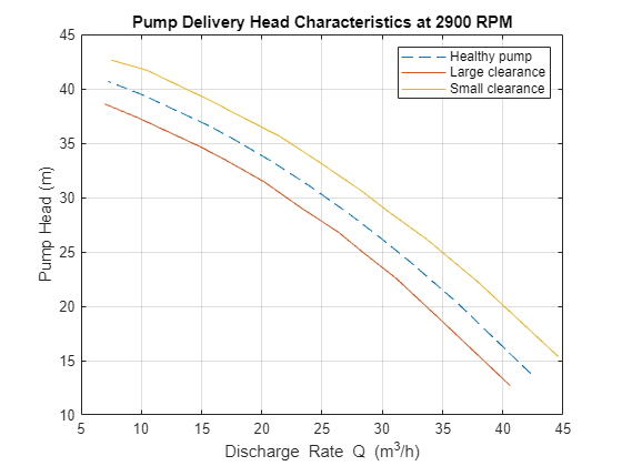
토크 흐름 특성과 그 밖의 결함 유형에서도 비슷한 변화를 볼 수 있습니다.
결함 진단의 자동화를 위해, 관측된 변화를 수량 정보로 변환합니다. 이를 위한 신뢰할 수 있는 방법 하나는 앞서 플로팅한 헤드 흐름 특성 데이터에 파라미터화된 곡선을 피팅하는 것입니다. 펌프-파이프 동특성에 적용되는 방정식과 간소화된 토크 관계를 사용하여 다음과 같은 방정식을 구할 수 있습니다.
는 추정할 파라미터입니다. , 를 측정할 경우 선형 최소제곱으로 파라미터를 추정할 수 있습니다. 이들 파라미터가 결함 검출 및 진단 알고리즘 개발에 사용할 수 있는 특징입니다.
예비 분석: 파라미터 값 비교하기
위의 3개의 곡선에 대해 추정된 파라미터 값을 계산하고 플로팅합니다. , 의 측정된 값을 데이터로 사용하고 을 공칭 펌프 속도로 사용합니다.
w = 2900; % RPM
% Healthy pump
[hnn_0, hnv_0, hvv_0, k0_0, k1_0, k2_0] = linearFit(0, {w, Q0, H0, M0});
% Pump with large clearance
[hnn_1, hnv_1, hvv_1, k0_1, k1_1, k2_1] = linearFit(0, {w, Q1, H1, M1});
% Pump with small clearance
[hnn_2, hnv_2, hvv_2, k0_2, k1_2, k2_2] = linearFit(0, {w, Q2, H2, M2});
X = [hnn_0 hnn_1 hnn_2; hnv_0  hnv_1  hnv_2; hvv_0  hvv_1  hvv_2]';
disp(array2table(X,'VariableNames',{'hnn','hnv','hvv'},...
    'RowNames',{'Healthy','Large Clearance', 'Small Clearance'}))
                          hnn           hnv           hvv
                       __________    __________    _________

    Healthy            5.1164e-06    8.6148e-05     0.010421
    Large Clearance     4.849e-06     8.362e-05     0.011082
    Small Clearance    5.3677e-06    8.4764e-05    0.0094656
Y = [k0_0 k0_1 k0_2; k1_0  k1_1  k1_2; k2_0  k2_1  k2_2]';
disp(array2table(Y,'VariableNames',{'k0','k1','k2'},...
    'RowNames',{'Healthy','Large Clearance', 'Small Clearance'}))
                           k0           k1           k2
                       __________    ________    __________

    Healthy            0.00033347    0.016535    2.8212e-07
    Large Clearance    0.00031571    0.016471    3.0285e-07
    Small Clearance    0.00034604    0.015886    2.6669e-07
표를 보면 조립 틈새가 클 때 과 값이 작아지고 조립 틈새가 작을 때 공칭 값보다 커짐을 알 수 있습니다. 반면 , 값은 조립 틈새가 클 때 커지고 조립 틈새가 작을 때 작아집니다. 및 의 경우 조립 틈새에 대한 종속성이 덜 확실합니다.
불확실성 고려하기
예비 분석 결과 파라미터 변화가 결함을 나타낼 수 있음을 알았습니다. 그러나 정상 펌프의 경우에도 측정 잡음, 유체 오염, 점도 변화, 펌프를 구동하는 모터의 슬립 토크 특성으로 인해 측정값이 달라질 수 있습니다. 이러한 측정값 변동으로 인해 파라미터 추정값의 불확실성이 발생합니다.
결함 없음 상태에서 작동하는 펌프를 10개의 배출 스로틀 밸브 위치에서 2900RPM으로 구동하여 측정값 세트 5개를 수집합니다.
url = 'https://www.mathworks.com/supportfiles/predmaint/fault-diagnosis-of-centrifugal-pumps-using-steady-state-experiments/FaultDiagnosisData.mat';
websave('FaultDiagnosisData.mat',url);
load FaultDiagnosisData HealthyEnsemble
H = cellfun(@(x)x.Head,HealthyEnsemble,'uni',0);
Q = cellfun(@(x)x.Discharge,HealthyEnsemble,'uni',0);
plot(cat(2,Q{:}),cat(2,H{:}),'k.')
title('Pump Head Characteristics Ensemble for 5 Test Runs')
xlabel('Flow rate (m^3/hed)')
ylabel('Pump head (m)')
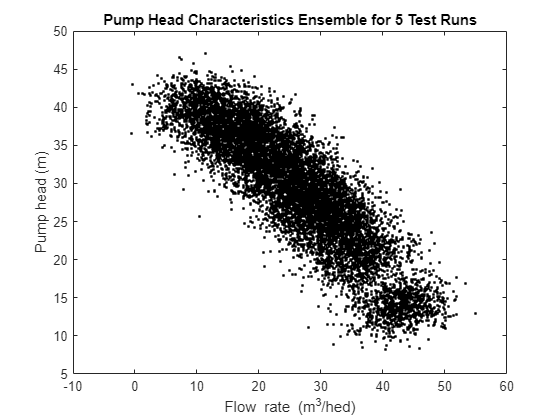
플롯을 보면 실제 상태에서는 정상 펌프의 경우에도 특성에 변동이 있음을 알 수 있습니다. 결함 진단이 신뢰성을 가지려면 이러한 변동을 고려해야 합니다. 다음 섹션에서는 잡음이 있는 데이터에 대한 결함 검출 및 분리 기법에 대해 설명합니다.
이상 감지
정상 기계의 측정값만 사용할 수 있는 경우가 많습니다. 이 경우 사용 가능한 측정값을 사용하여 파라미터 벡터의 평균값과 공분산으로 캡슐화된 정상 상태에 대한 통계 기술을 만들 수 있습니다. 테스트 펌프의 측정값을 공칭 통계량과 비교하여 테스트 펌프가 정상 펌프일 수 있는지 테스트할 수 있습니다. 결함 있는 펌프라면 검출 특징을 표시했을 때 이상 상태로 감지될 것으로 예상됩니다.
펌프 헤드 및 토크 파라미터의 평균과 공분산을 추정합니다.
load FaultDiagnosisData HealthyEnsemble
[HealthyTheta1, HealthyTheta2] = linearFit(1, HealthyEnsemble);
meanTheta1 = mean(HealthyTheta1,1);
meanTheta2 = mean(HealthyTheta2,1);
covTheta1  = cov(HealthyTheta1);
covTheta2  = cov(HealthyTheta2);
파라미터 불확실성을 2 표준편차에 해당하는 74% 신뢰영역으로 시각화합니다(). 자세한 내용은 헬퍼 함수 helperPlotConfidenceEllipsoid를 참조하십시오.
% Confidence ellipsoid for pump head parameters
f = figure;
f.Position(3) = f.Position(3)*2;
subplot(121)
helperPlotConfidenceEllipsoid(meanTheta1,covTheta1,2,0.6);
xlabel('hnn')
ylabel('hnv')
zlabel('hvv')
title('2-sd Confidence Ellipsoid for Pump Head Parameters')
hold on
% Confidence ellipsoid for pump torque parameters
subplot(122)
helperPlotConfidenceEllipsoid(meanTheta2,covTheta2,2,0.6);
xlabel('k0')
ylabel('k1')
zlabel('k2')
title('2-sd Confidence Ellipsoid for Pump Torque Parameters')
hold on
회색 타원체는 정상 펌프 파라미터의 신뢰영역을 보여줍니다. 정상 영역과의 비교를 위해 레이블이 지정되지 않은 테스트 데이터를 불러옵니다.
load FaultDiagnosisData TestEnsemble
TestEnsemble은 여러 밸브 위치에서의 펌프 속도, 토크, 헤드 및 유량 측정값을 포함합니다. 모든 측정값은 서로 다른 크기의 조립 틈새 결함을 포함합니다.
% Test data preview
disp(TestEnsemble{1}(1:5,:)) % first 5 measurement rows from the first ensemble member
      Time       Run    ValvePosition    Speed      Head     Discharge    Torque
    _________    ___    _____________    ______    ______    _________    _______

    180 sec       1          10          3034.6    12.367     35.339      0.35288
    180.1 sec     1          10          2922.1    9.6762     36.556       4.6953
    180.2 sec     1          10          2636.1    11.168     36.835       9.8898
    180.3 sec     1          10          2717.4    10.562      40.22      -12.598
    180.4 sec     1          10          3183.7     10.55     40.553       14.672
테스트 파라미터를 계산합니다. 헬퍼 함수 linearFit을 참조하십시오.
% TestTheta1: pump head parameters
% TestTheta2: pump torque parameters
[TestTheta1,TestTheta2] = linearFit(1, TestEnsemble);
subplot(121)
plot3(TestTheta1(:,1),TestTheta1(:,2),TestTheta1(:,3),'g*')
view([-42.7 10])
subplot(122)
plot3(TestTheta2(:,1),TestTheta2(:,2),TestTheta2(:,3),'g*')
view([-28.3 18])
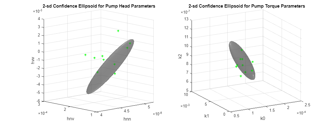
테스트 펌프 하나가 녹색 별표 마커 하나에 해당합니다. 신뢰한계 밖에 있는 마커는 이상값으로 취급할 수 있고, 신뢰한계 안에 있는 마커는 정상 펌프이거나 검출에 걸리지 않은 것으로 취급할 수 있습니다. 어떤 펌프의 마커는 펌프 헤드에서는 이상값으로 표시되지만 펌프 토크에서는 이상값이 아닌 경우가 있을 수 있습니다. 이는 각각이 서로 다른 결함 원인을 감지했기 때문이거나 압력 및 토크 측정값의 기본 신뢰성 때문일 수 있습니다.
신뢰영역을 사용하여 이상 감지 수량화하기
이 섹션에서는 결함의 검출 및 심각도 평가에 신뢰영역 정보를 사용하는 방법을 설명합니다. 이 기법은 정상 영역 분포의 평균 또는 중앙값에서 테스트 샘플까지의 "거리"를 계산하는 것입니다. 거리는 공분산으로 나타나는 정상 파라미터 데이터의 정상 "산포"에 상대적이어야 합니다. 함수 MAHAL은 기준 샘플 세트(여기서는 정상 펌프 파라미터 세트)의 분포에서 테스트 샘플의 마할라노비스 거리를 계산합니다.
ParDist1 = mahal(TestTheta1, HealthyTheta1); % for pump head parameters정상 데이터에 대해 허용되는 변동을 74% 신뢰한계(2 표준편차)로 가정할 경우, ParDist1에서 2^2 = 4보다 큰 모든 값은 이상값으로 태그가 지정되어야 하며 이는 결함 동작을 나타냅니다.
플롯에 거리 값을 추가합니다. 빨간색 선은 이상 테스트 샘플을 표시합니다. 헬퍼 함수 helperAddDistanceLines를 참조하십시오.
Threshold = 2;
disp(table((1:length(ParDist1))',ParDist1, ParDist1>Threshold^2,...
    'VariableNames',{'PumpNumber','SampleDistance','Anomalous'}))
    PumpNumber    SampleDistance    Anomalous
    __________    ______________    _________

         1            58.874          true
         2            24.051          true
         3             6.281          true
         4            3.7179          false
         5             13.58          true
         6            3.0723          false
         7            2.0958          false
         8            4.7127          true
         9            26.829          true
        10           0.74682          false
helperAddDistanceLines(1, ParDist1, meanTheta1, TestTheta1, Threshold);
마찬가지로 펌프 토크에 대해서도 다음이 성립합니다.
ParDist2 = mahal(TestTheta2, HealthyTheta2);  % for pump torque parameters
disp(table((1:length(ParDist2))',ParDist2, ParDist2>Threshold^2,...
    'VariableNames',{'PumpNumber','SampleDistance','Anomalous'}))
    PumpNumber    SampleDistance    Anomalous
    __________    ______________    _________

         1            9.1381          true
         2            5.4249          true
         3            3.0565          false
         4             3.775          false
         5           0.77961          false
         6            7.5508          true
         7            3.3368          false
         8           0.74834          false
         9            3.6478          false
        10            1.0241          false
helperAddDistanceLines(2, ParDist2, meanTheta2, TestTheta2, Threshold);
view([8.1 17.2])
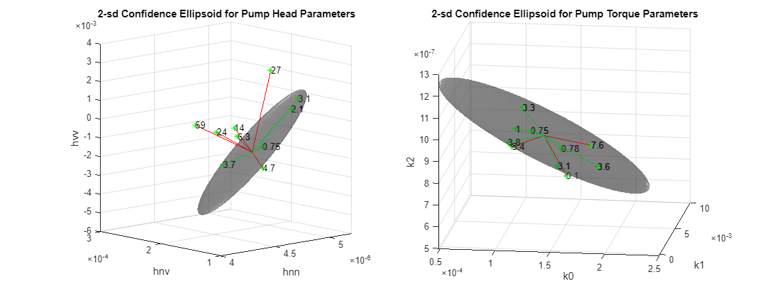
플롯은 이상 샘플의 검출을 보여줄 뿐 아니라 그 심각도도 수량화합니다.
단일 클래스 분류기를 사용하여 이상 감지 수량화하기
이상값에 플래그를 지정하는 또 다른 효과적인 기법은 정상 파라미터 데이터셋에 대해 단일 클래스 분류기를 만드는 것입니다. 정상 펌프 파라미터 데이터를 사용하여 SVM 분류기를 훈련시킵니다. 결함 없음 레이블이 사용되었으므로 모든 샘플이 동일한(정상) 클래스에서 온 것으로 처리합니다. 파라미터 및 의 변화가 잠재적인 결함을 가장 잘 나타내므로, 이들 파라미터만 사용하여 SVM 분류기를 훈련시킵니다.
nc = size(HealthyTheta1,1);
rng(2)  % for reproducibility
SVMOneClass1 = fitcsvm(HealthyTheta1(:,[1 3]),ones(nc,1),...
    'KernelScale','auto',...
    'Standardize',true,...
    'OutlierFraction',0.0455);
테스트 관측값과 결정 경계를 플로팅합니다. 서포트 벡터와 잠재적인 이상값에 플래그를 지정합니다. 헬퍼 함수 helperPlotSVM을 참조하십시오.
figure
helperPlotSVM(SVMOneClass1,TestTheta1(:,[1 3]))
title('SVM Anomaly Detection for Pump Head Parameters')
xlabel('hnn')
ylabel('hvv')
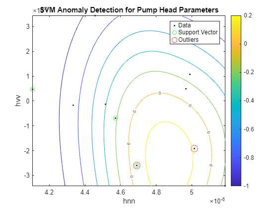
이상값을 나머지 데이터와 분리하는 경계는 등고선 값이 0인 위치에서 나타납니다. 이는 플롯에서 "0"으로 표시된 등위선입니다. 이상값은 빨간색 원으로 표시되었습니다. 토크 파라미터에 대해서도 유사한 분석을 수행할 수 있습니다.
SVMOneClass2 = fitcsvm(HealthyTheta2(:,[1 3]),ones(nc,1),...
    'KernelScale','auto',...
    'Standardize',true,...
    'OutlierFraction',0.0455);
figure
helperPlotSVM(SVMOneClass2,TestTheta2(:,[1 3]))
title('SVM Anomaly Detection for Torque Parameters')
xlabel('k0')
ylabel('k2')
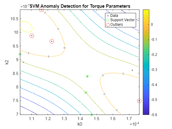
뒤에서 결함 분리라는 맥락에서 설명하는 것처럼 임펠러 출구의 마모나 침전과 같은 다른 유형의 결함 검출에 대해서도 유사한 분석을 수행할 수 있습니다.
정상 상태 파라미터를 특징으로 사용한 결함 분리
테스트 시스템의 결함 유형에 대한 정보가 있는 경우, 이 정보를 사용하여 결함을 검출할 뿐 아니라 결함의 유형까지 나타내는 알고리즘을 만들 수 있습니다.
A. 가능도비 검정으로 조립 틈새 결함 구분하기
조립 틈새 변화는 예상 틈새보다 작은 경우(펌프 헤드 특성 플롯의 노란색 선)와 예상 틈새보다 큰 경우(빨간색 선)의 두 가지 유형으로 나눌 수 있습니다. 조립 틈새 결함을 포함하면서 결함의 성격(큰 틈새인지 작은 틈새인지 여부)을 이미 알고 있는 펌프 테스트 데이터 세트를 불러옵니다. 결함 레이블을 사용하여 다음과 같은 모드를 기준으로 3방향 분류를 수행합니다.
모드 1: 정상 조립 틈새(정상 동작)
모드 2: 큰 조립 틈새
모드 3: 작은 조립 틈새
url = 'https://www.mathworks.com/supportfiles/predmaint/fault-diagnosis-of-centrifugal-pumps-using-steady-state-experiments/LabeledGapClearanceData.mat';
websave('LabeledGapClearanceData.mat',url);
load LabeledGapClearanceData HealthyEnsemble LargeGapEnsemble SmallGapEnsemble
앙상블은 50개의 독립 실험으로부터 생성된 데이터를 포함합니다. 정상 상태 선형 모델을 전과 같이 피팅하여 펌프 헤드 및 토크 데이터를 파라미터화합니다.
[HealthyTheta1, HealthyTheta2] = linearFit(1,HealthyEnsemble);
[LargeTheta1, LargeTheta2]     = linearFit(1,LargeGapEnsemble);
[SmallTheta1, SmallTheta2]     = linearFit(1,SmallGapEnsemble);
파라미터 히스토그램을 플로팅하여 3개 모드 사이가 분리되는지 확인합니다. 히스토그램과 대응하는 피팅된 정규분포 곡선을 플로팅하는 데 함수 histfit이 사용됩니다. 헬퍼 함수 helperPlotHistogram을 참조하십시오.
펌프 헤드 파라미터:
helperPlotHistogram(HealthyTheta1, LargeTheta1, SmallTheta1, {'hnn','hnv','hvv'})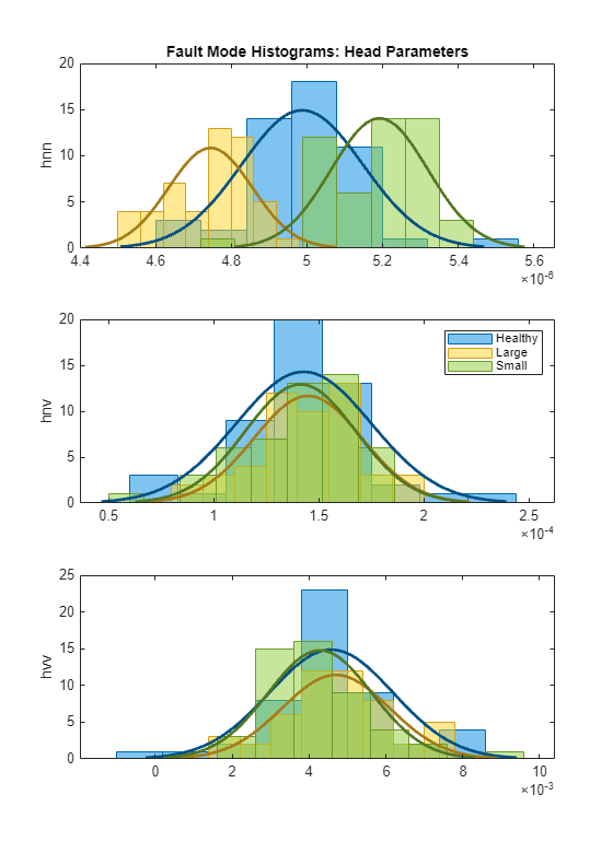
히스토그램에서 은 세 개 모드를 제대로 분리하지만 파라미터는 확률 분포 함수(PDF)가 겹치는 것을 볼 수 있습니다.
펌프 토크 파라미터:
helperPlotHistogram(HealthyTheta2, LargeTheta2, SmallTheta2, {'k0','k1','k2'})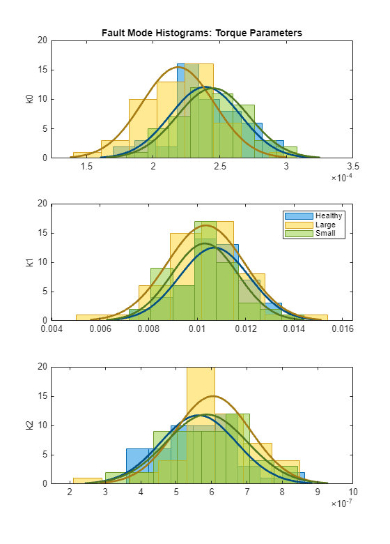
토크 파라미터의 경우 개별 분리도가 좋지 않습니다. 평균 및 분산에 훈련된 3모드 분류기를 통해 활용할 수 있는 얼마간의 변동이 여전히 있습니다. PDF가 평균 또는 분산을 제대로 분리하는 경우, 가능도비 검정을 설계하여 가장 가능성이 높은 모드에 테스트 데이터셋을 빠르게 할당할 수 있습니다. 아래에 펌프 헤드 파라미터에 대한 가능성비 검정이 나와 있습니다.
다음과 같이 가정하겠습니다.
: 헤드 파라미터가 정상 펌프 모드에 속한다는 가설
: 헤드 파라미터가 조립 틈새가 큰 펌프에 속한다는 가설
: 헤드 파라미터가 조립 틈새가 작은 펌프에 속한다는 가설
사용 가능한 파라미터 세트를 모드 예측을 위한 테스트 샘플로 간주합니다. 예측된 모드를 결합 PDF가 가장 높은 값을 갖는 모드에 속하는 것으로 할당합니다(인 경우 가설 대신 이 선택됨). 그런 다음 혼동행렬에 실제 모드와 예측된 모드를 비교하는 결과를 플로팅합니다. 함수 mvnpdf는 PDF 값을 계산하는 데 사용되고 함수 confusionmatrix와 heatmap은 혼동행렬 시각화에 사용됩니다. 헬퍼 함수 pumpModeLikelihoodTest를 참조하십시오.
% Pump head confusion matrix
figure
pumpModeLikelihoodTest(HealthyTheta1, LargeTheta1, SmallTheta1)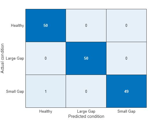
정오 플롯은 세 가지 모드 사이의 완벽한 분리를 보여줍니다. 파라미터의 히스토그램에서 명확한 분리를 확인할 수 있었으므로 당연한 결과입니다.
% Pump torque confusion matrix
pumpModeLikelihoodTest(HealthyTheta2, LargeTheta2, SmallTheta2)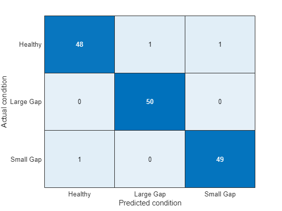
결과는 토크 파라미터보다 약간 나쁩니다. 그렇지만 세 개 모드의 PDF가 상당히 겹쳤음에도 불구하고 성공률이 꽤 높습니다(97%). 이는 PDF 값 계산에 위치(평균)와 진폭(분산)이 모두 영향을 주기 때문입니다.
B. 트리 배깅을 사용한 결함 모드의 다중 클래스 분류
이 섹션에서는 더 많은 수의 모드로 분류해야 하는 경우에 적합한 분류 기법에 대해 설명합니다. 펌프 작동에서 다음과 같은 결함 모드를 살펴보겠습니다.
정상 작동
조립 틈새의 마모
임펠러 출구의 작은 침전
임펠러 주입구의 침전
임펠러 출구의 연삭 마모
부러진 블레이드
공동 현상
계산되는 파라미터는 3개밖에 되지 않는데 작동 모드는 7개를 구분해야 하므로 분류 문제가 더 어려워졌습니다. 따라서 각 결함 모드의 추정된 파라미터를 정상 모드와 비교해야 할 뿐 아니라 결함 모드 간의 파라미터도 비교해야 합니다. 즉, 파라미터 변화의 방향(값의 증가 또는 감소)과 크기(10% 변화 대 70% 변화)도 고려해야 합니다.
아래에는 이 문제를 위해 TreeBagger 분류기를 사용하는 방법이 나와 있습니다. TreeBagger는 특징의 부트스트랩 집계(배깅)를 사용하여 레이블이 지정된 데이터를 분류하는 결정 트리를 만드는 앙상블 학습 기법입니다. 7개의 작동 모드에 대해 레이블이 지정된 데이터 세트 50개가 수집되었습니다. 각 데이터셋에 대해 펌프 헤드 파라미터를 추정하고, 각 모드의 파라미터 추정값 서브셋을 사용하여 분류기를 훈련시킵니다.
url = 'https://www.mathworks.com/supportfiles/predmaint/fault-diagnosis-of-centrifugal-pumps-using-steady-state-experiments/MultipleFaultsData.mat';
websave('MultipleFaultsData.mat',url);
load MultipleFaultsData
% Compute pump head parameters
HealthyTheta = linearFit(1, HealthyEnsemble);
Fault1Theta  = linearFit(1, Fault1Ensemble);
Fault2Theta  = linearFit(1, Fault2Ensemble);
Fault3Theta  = linearFit(1, Fault3Ensemble);
Fault4Theta  = linearFit(1, Fault4Ensemble);
Fault5Theta  = linearFit(1, Fault5Ensemble);
Fault6Theta  = linearFit(1, Fault6Ensemble);

% Generate labels for each mode of operation
Label = {'Healthy','ClearanceGapWear','ImpellerOutletDeposit',...
    'ImpellerInletDeposit','AbrasiveWear','BrokenBlade','Cavitation'};
VarNames = {'hnn','hnv','hvv','Condition'};
% Assemble results in a table with parameters and corresponding labels
N = 50;
T0 = [array2table(HealthyTheta),repmat(Label(1),[N,1])];
T0.Properties.VariableNames = VarNames;
T1 = [array2table(Fault1Theta), repmat(Label(2),[N,1])];
T1.Properties.VariableNames = VarNames;
T2 = [array2table(Fault2Theta), repmat(Label(3),[N,1])];
T2.Properties.VariableNames = VarNames;
T3 = [array2table(Fault3Theta), repmat(Label(4),[N,1])];
T3.Properties.VariableNames = VarNames;
T4 = [array2table(Fault4Theta), repmat(Label(5),[N,1])];
T4.Properties.VariableNames = VarNames;
T5 = [array2table(Fault5Theta), repmat(Label(6),[N,1])];
T5.Properties.VariableNames = VarNames;
T6 = [array2table(Fault6Theta), repmat(Label(7),[N,1])];
T6.Properties.VariableNames = VarNames;

% Stack all data
% Use 30 out of 50 datasets for model creation
TrainingData = [T0(1:30,:);T1(1:30,:);T2(1:30,:);T3(1:30,:);T4(1:30,:);T5(1:30,:);T6(1:30,:)];

% Create an ensemble Mdl of 20 decision trees for predicting the
% labels using the parameter values
rng(3) % for reproducibility
Mdl = TreeBagger(20, TrainingData, 'Condition',...
   'OOBPrediction','on',...
   'OOBPredictorImportance','on')
Mdl =
  TreeBagger
Ensemble with 20 bagged decision trees:
                    Training X:              [210x3]
                    Training Y:              [210x1]
                        Method:       classification
                 NumPredictors:                    3
         NumPredictorsToSample:                    2
                   MinLeafSize:                    1
                 InBagFraction:                    1
         SampleWithReplacement:                    1
          ComputeOOBPrediction:                    1
 ComputeOOBPredictorImportance:                    1
                     Proximity:                   []
                    ClassNames:  'AbrasiveWear'   'BrokenBlade'    'Cavitation' 'ClearanceGapWear'       'Healthy' 'ImpellerInletDeposit' 'ImpellerOutletDeposit'

  Properties, Methods
TreeBagger 모델의 성능은 Out-of-bag 관측값의 오분류 확률을 결정 트리 개수의 함수로 살펴봄으로써 계산할 수 있습니다.
% Compute out of bag error
figure
plot(oobError(Mdl))
xlabel('Number of trees')
ylabel('Misclassification probability')
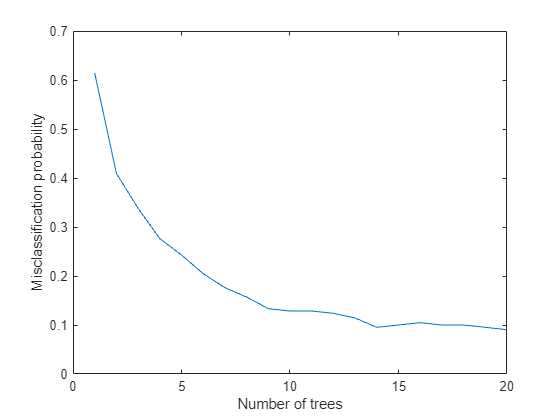
마지막으로, 결정 트리를 구성하는 데 사용되지 않은 테스트 샘플에 대해 모델의 예측 성능을 계산합니다.
ValidationData = [T0(31:50,:);T1(31:50,:);T2(31:50,:);T3(31:50,:);T4(31:50,:);T5(31:50,:);T6(31:50,:)];
PredictedClass = predict(Mdl,ValidationData);
E = zeros(1,7);
% Healthy data misclassification
E(1) = sum(~strcmp(PredictedClass(1:20), Label{1}));
% Clearance gap fault misclassification
E(2) = sum(~strcmp(PredictedClass(21:40), Label{2}));
% Impeller outlet deposit fault misclassification
E(3) = sum(~strcmp(PredictedClass(41:60), Label{3}));
% Impeller inlet deposit fault misclassification
E(4) = sum(~strcmp(PredictedClass(61:80), Label{4}));
% Abrasive wear fault misclassification
E(5) = sum(~strcmp(PredictedClass(81:100), Label{5}));
% Broken blade fault misclassification
E(6) = sum(~strcmp(PredictedClass(101:120), Label{6}));
% Cavitation fault misclassification
E(7) = sum(~strcmp(PredictedClass(121:140), Label{7}));
figure
bar(E/20*100)
xticklabels(Label)
set(gca,'XTickLabelRotation',45)
ylabel('Misclassification (%)')
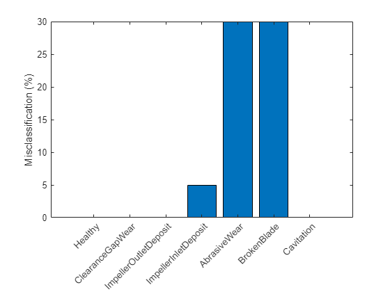
플롯은 검증 샘플의 30%에 대해 연삭 마모 결함과 부러진 블레이드 결함이 오분류되었음을 보여줍니다. 예측된 레이블을 보다 자세히 살펴보면 오분류된 사례의 경우 'AbrasiveWear' 레이블과 'BrokenBlade' 레이블이 서로만 섞인다는 사실을 알 수 있습니다. 이는 이 분류기에서 이들 결함 범주의 증상을 충분히 분간할 수 없음을 나타냅니다.
요약
결함 진단 전략을 잘 설계하면 서비스 가동 중단 시간 및 부품 교체 비용을 최소화하여 운영 비용을 절감할 수 있습니다. 작동하는 기계의 동특성에 대한 지식과 센서 측정값을 함께 사용하여 여러 종류의 결함을 검출하고 분리하면 훌륭한 전략을 수립할 수 있습니다.
이 예제에서는 정상 상태 실험을 기반으로 결함 검출 및 분리에 파라미터화된 접근 방식을 사용하는 방법을 설명했습니다. 이 접근 방식을 사용하려면 시스템 동특성을 신중히 모델링하고 파라미터(또는 파라미터의 변환)를 결함 진단 알고리즘 설계를 위한 특성으로 사용해야 합니다. 파라미터는 이상 감지기의 훈련, 가능도비 검정 수행과 다중 클래스 분류기 훈련에 사용되었습니다.
실제 펌프 테스트에서 분류 기법을 사용하는 방법
다음은 결함 진단 워크플로의 요약입니다.
테스트 펌프를 공칭 속도로 구동합니다. 배출 밸브를 여러 설정으로 회전하여 유량을 제어합니다. 각 밸브 위치에 대해 펌프 속도, 유량, 차동 압력, 토크를 기록합니다.
펌프 헤드 및 펌프 토크 특성(정상 상태) 방정식의 파라미터를 추정합니다.
불확실성/잡음이 낮고 파라미터 추정값을 신뢰할 수 있는 경우, 추정된 파라미터를 공칭 값과 직접 비교할 수 있습니다. 상대 크기는 결함의 성격을 나타냅니다.
일반적인 잡음이 있는 상황에서는 이상 감지 기법을 사용하여 시스템에 결함이 존재하는지 여부를 먼저 확인합니다. 추정된 파라미터 값을 정상 펌프의 과거 데이터베이스에서 얻은 평균 및 공분산 값과 비교하면 빠르게 확인할 수 있습니다.
결함이 있음을 나타내는 경우, 결함 분류 기법(가능도비 검정, 분류기 출력값 등)을 사용하여 가장 가능한 원인을 분리합니다. 어느 분류기 기법을 선택하는지는 사용 가능한 센서 데이터, 데이터의 신뢰성, 결함의 심각도, 결함 모드와 관련된 과거 정보의 사용 가능 여부에 따라 달라집니다.
잔차 분석을 기반으로 하는 결함 진단 접근 방식은 잔차 분석을 사용한 원심 펌프의 결함 진단 예제를 참조하십시오.
참고 문헌
Isermann, Rolf, Fault-Diagnosis Applications. Model-Based Condition Monitoring: Actuators, Drives, Machinery, Plants, Sensors, and Fault-tolerant System, Edition 1, Springer-Verlag Berlin Heidelberg, 2011.
지원 함수
펌프 파라미터에 대해 선형 피팅을 수행합니다.
function varargout = linearFit(Form, Data)
%linearFit Linear least squares solution for Pump Head and Torque parameters.
%
% If Form==0, accept separate inputs and return separate outputs. For one experiment only.
% If Form==1, accept an ensemble and return compact parameter vectors. For several experiments (ensemble).
if Form==0
   w = Data{1};
   Q = Data{2};
   H = Data{3};
   M = Data{4};
   n = length(Q);
   if isscalar(w), w = w*ones(n,1); end
   Q = Q(:); H = H(:); M = M(:);
   Predictor = [w.^2, w.*Q, Q.^2];
   Theta1 = Predictor\H;
   hnn =  Theta1(1);
   hnv = -Theta1(2);
   hvv = -Theta1(3);
   Theta2 = Predictor\M;
   k0 =  Theta2(2);
   k1 = -Theta2(3);
   k2 =  Theta2(1);
   varargout = {hnn, hnv, hvv, k0, k1, k2};
else
   H = cellfun(@(x)x.Head,Data,'uni',0);
   Q = cellfun(@(x)x.Discharge,Data,'uni',0);
   M = cellfun(@(x)x.Torque,Data,'uni',0);
   W = cellfun(@(x)x.Speed,Data,'uni',0);
   N = numel(H);

   Theta1 = zeros(3,N);
   Theta2 = zeros(3,N);

   for kexp = 1:N
      Predictor = [W{kexp}.^2, W{kexp}.*Q{kexp}, Q{kexp}.^2];
      X1 = Predictor\H{kexp};
      hnn =  X1(1);
      hnv = -X1(2);
      hvv = -X1(3);
      X2 = Predictor\M{kexp};
      k0 =  X2(2);
      k1 = -X2(3);
      k2 =  X2(1);

      Theta1(:,kexp) = [hnn; hnv; hvv];
      Theta2(:,kexp) = [k0; k1; k2];
   end
   varargout = {Theta1', Theta2'};
end
end
멤버 소속에 대한 가능성비 검정을 수행합니다.
function pumpModeLikelihoodTest(HealthyTheta, LargeTheta, SmallTheta)
%pumpModeLikelihoodTest Generate predictions based on PDF values and plot confusion matrix.

m1 = mean(HealthyTheta);
c1 = cov(HealthyTheta);
m2 = mean(LargeTheta);
c2 = cov(LargeTheta);
m3 = mean(SmallTheta);
c3 = cov(SmallTheta);

N = size(HealthyTheta,1);

% True classes
% 1: Healthy: group label is 1.
X1t = ones(N,1);
% 2: Large gap: group label is 2.
X2t = 2*ones(N,1);
% 3: Small gap: group label is 3.
X3t = 3*ones(N,1);

% Compute predicted classes as those for which the joint PDF has the maximum value.
X1 = zeros(N,3);
X2 = zeros(N,3);
X3 = zeros(N,3);
for ct = 1:N
   % Membership probability density for healthy parameter sample
   HealthySample  = HealthyTheta(ct,:);
   x1 = mvnpdf(HealthySample, m1, c1);
   x2 = mvnpdf(HealthySample, m2, c2);
   x3 = mvnpdf(HealthySample, m3, c3);
   X1(ct,:) = [x1 x2 x3];

   % Membership probability density for large gap pump parameter
   LargeSample  = LargeTheta(ct,:);
   x1 = mvnpdf(LargeSample, m1, c1);
   x2 = mvnpdf(LargeSample, m2, c2);
   x3 = mvnpdf(LargeSample, m3, c3);
   X2(ct,:) = [x1 x2 x3];

   % Membership probability density for small gap pump parameter
   SmallSample  = SmallTheta(ct,:);
   x1 = mvnpdf(SmallSample, m1, c1);
   x2 = mvnpdf(SmallSample, m2, c2);
   x3 = mvnpdf(SmallSample, m3, c3);
   X3(ct,:) = [x1 x2 x3];
end

[~,PredictedGroup] = max([X1;X2;X3],[],2);
TrueGroup = [X1t; X2t; X3t];
C = confusionmat(TrueGroup,PredictedGroup);
heatmap(C, ...
    'YLabel', 'Actual condition', ...
    'YDisplayLabels', {'Healthy','Large Gap','Small Gap'}, ...
    'XLabel', 'Predicted condition', ...
    'XDisplayLabels', {'Healthy','Large Gap','Small Gap'}, ...
    'ColorbarVisible','off');
end