Verify Generated Code by Using Cosimulation
Verify your generated code by using cosimulation. The generated code and testbench run on a CODESYS software-based programmable logic controller (SoftPLC). The Simulink® model uses Open Platform Communication Unified Architecture (OPC UA) to communicate with and retrieve the co-simulation data from the SoftPLC. The Simulink model verifies the generated code by comparing the model simulation results to the co-simulation SoftPLC results.
Prerequisites
On your system, you must have installed:
CODESYS V3.5.SP16 + IDE or CODESYS V3.5 SP16 Patch 1 + IDE
Industrial Communication Toolbox™
Simulink PLC Coder™
Model Description
The simple_cosim model is made up of the SimpleSubsystem block and the MATLAB System (PLCCOSIM) block. During simulation, the model compares values from the SimpleSubsystem block to the values from the SoftPLC which are retrieved by using the MATLAB System (PLCCOSIM) block.
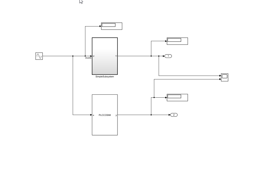
The SimpleSubsystem block contains a simple feedback loop.

The MATLAB System block is set up to run the PLCCOSIM.m file. The file contains the code to set up OPC UA communications and retrieve the co-simulation data from the SoftPLC.
type PLCCOSIM.mclassdef PLCCOSIM < matlab.System
% PLCCOSIM Add summary here
%
% This template includes the minimum set of functions required
% to define a System object with discrete state.
% Public, tunable properties
properties
end
properties(DiscreteState)
CycleNum;
end
% Pre-computed constants
properties(Access = private)
UAObj;
DeviceNode;
Cycle_U;
Cycle_Y;
TestCycleNum;
PreviousCycleNum;
end
methods(Access = protected)
function setupImpl(obj)
% Perform one-time calculations, such as computing constants
% init opc UA server connection
obj.UAObj = opcua('opc.tcp://localhost:4840');
connect(obj.UAObj);
obj.DeviceNode = findNodeByName(obj.UAObj.Namespace,'DeviceSet','-once');
obj.Cycle_U = findNodeByName(obj.DeviceNode,'cycle_U');
obj.Cycle_Y = findNodeByName(obj.DeviceNode,'cycle_Y');
obj.TestCycleNum = findNodeByName(obj.DeviceNode,'testCycleNum');
obj.PreviousCycleNum = findNodeByName(obj.DeviceNode,'previousCycleNum');
end
function y = stepImpl(obj,u)
% Implement algorithm. Calculate y as a function of input u and
% discrete states.
obj.CycleNum = obj.CycleNum+1;
writeValue(obj.UAObj, obj.Cycle_U, u);
writeValue(obj.UAObj, obj.TestCycleNum, obj.CycleNum);
valueUpdated = false;
for rct = 1:100
previousCycleNumValue = readValue(obj.UAObj, obj.PreviousCycleNum);
if previousCycleNumValue == obj.CycleNum
valueUpdated = true;
y = readValue(obj.UAObj, obj.Cycle_Y);
break
end
pause(0.001)
end
if ~valueUpdated
error('not get the value for cycle number %d', obj.CycleNum);
end
end
function resetImpl(obj)
% Initialize / reset discrete-state properties
obj.CycleNum = 0;
writeValue(obj.UAObj, obj.TestCycleNum, obj.CycleNum);
writeValue(obj.UAObj, obj.PreviousCycleNum, obj.CycleNum);
end
function out = getOutputSizeImpl(obj)
out = propagatedInputSize(obj,1);
end
function out = getOutputDataTypeImpl(obj)
out = propagatedInputDataType(obj,1);
end
function c1 = isOutputComplexImpl(obj)
c1 = false;
end
function c1 = isOutputFixedSizeImpl(obj)
c1 = true;
end
function s = getDiscreteStateImpl(obj)
s = obj.CycleNum;
end
end
end
Compile, and Simulate the CODESYS Project
The CODESYS project file runs the generated code on the SoftPLC. If you have the CODESYS V3.5.SP16 + IDE, use the plc-cosim_v3sp16.project as the project file. If you have the CODESYS V3.5.SP16 Patch 1+ IDE, use the plc-cosim_v3sp16patch1.project as the project file.
In the Windows® system tray, select CODESYS Control Win SysTray -x64, right-click, and select Start PLC.
Open the project file based on the CODESYS Target IDE version.
Double-click CODESYS
_Control_Win_V3_x64and select Scan Network.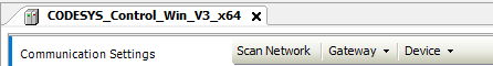
In the Scan Network tab, select your device in the Select Device window. Click OK.

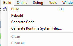
Select Build > Build.
6.Select Online > Login.
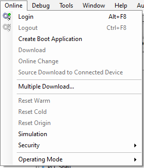
7. Select Debug > Start.

The SoftPLC runs the generated code.
Simulate the Model and Verify Generated Code
Simulate the Simulink model and verify the generated code by comparing the simulation model results to the SoftPLC results. The SoftPLC results are retrieved by using the OPC UA connection.
Open the
simple_cosim.slxfile for the Simulink model.
% open_system('simple_cosim')2. Simulate the model. Verify the generated code by comparing the model simulation results to the SoftPLC co-simulation results.