Thermal Deflection of Bimetallic Beam
This example shows how to solve a coupled thermo-elasticity problem. Thermal expansion or contraction in mechanical components and structures occurs due to temperature changes in the operating environment. Thermal stress is a secondary manifestation: the structure experiences stresses when structural constraints prevent free thermal expansion or contraction of the component. Deflection of a bimetallic beam is a common physics experiment. A typical bimetallic beam consists of two materials bonded together. The coefficients of thermal expansion (CTE) of these materials are significantly different.

This example finds the deflection of a bimetallic beam and compares this deflection to the analytic solution based on beam theory approximation.
Create a beam geometry with these dimensions.
L = 0.1; % m
W = 5e-3; % m
H = 1e-3; % m
gm = multicuboid(L,W,[H,H],Zoffset=[0,H]);
Plot the geometry.
figure
pdegplot(gm)

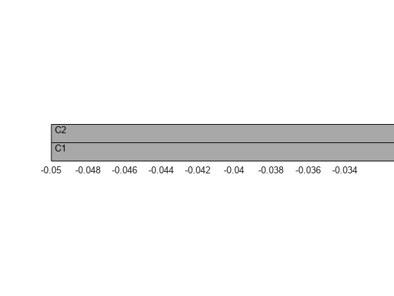
Identify the cell labels of the cells for which you want to specify material properties.
figure
pdegplot(gm,CellLabels="on")
axis([-L/2 -L/3 -W/2 W/2 0 2*H])
view([0 0])
zticks([])
Create an femodel object for static structural analysis and include the geometry.
model = femodel(AnalysisType="structuralStatic", ...
                Geometry=gm);
Specify Young's modulus, Poisson's ratio, and the linear coefficient of thermal expansion to model linear elastic material behavior. To maintain unit consistency, specify all physical properties in SI units. First, assign the material properties of copper to the bottom cell.
Ec = 137e9; % N/m^2
nuc = 0.28;
CTEc = 20.00e-6; % m/m-C
model.MaterialProperties(1) = ...
    materialProperties(YoungsModulus=Ec, ...
                       PoissonsRatio=nuc, ...
                       CTE=CTEc);
Assign the material properties of invar to the top cell.
Ei = 130e9; % N/m^2
nui = 0.354;
CTEi = 1.2e-6; % m/m-C
model.MaterialProperties(2) = ...
    materialProperties(YoungsModulus=Ei, ...
                       PoissonsRatio=nui, ...
                       CTE=CTEi);
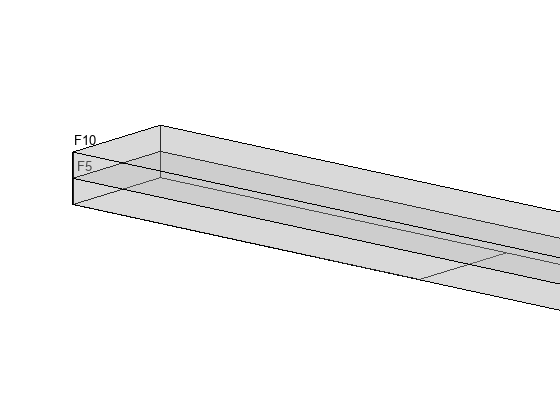
For this example, assume that the left end of the beam is fixed. To impose this boundary condition, display the face labels on the left end of the beam.
figure
pdegplot(gm,FaceLabels="on", ...
            FaceAlpha=0.25)
axis([-L/2 -L/3 -W/2 W/2 0 2*H])
view([40 15])
xticks([])
yticks([])
zticks([])

Apply a fixed boundary condition on faces 5 and 10.
model.FaceBC([5,10]) = faceBC(Constraint="fixed");Apply the temperature change as a thermal load. Use a reference temperature of 25 degrees Celsius and an operating temperature of 125 degrees Celsius. Thus, the temperature change for this model is 100 degrees Celsius.
model.CellLoad = cellLoad(Temperature=125);
model.ReferenceTemperature = 25;
Generate a mesh and solve the model.
model = generateMesh(model,Hmax=H/2);
R = solve(model);
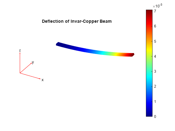
Plot the deflected shape of the bimetallic beam with the magnitude of displacement as the colormap data.
figure
pdeplot3D(R.Mesh,ColorMapData=R.Displacement.Magnitude, ...
                 Deformation=R.Displacement, ...
                 DeformationScaleFactor=2)
title("Deflection of Invar-Copper Beam")

You also can plot the deflected shape of the bimetallic beam with the magnitude of displacement as the colormap data by using the Visualize PDE Results Live Editor task. First, create a new live script by clicking the New Live Script button in the File section on the Home tab.

On the Live Editor tab, select Task > Visualize PDE Results. This action inserts the task into your script.

To plot the magnitude of displacement, follow these steps.
In the Select results section of the task, select
Rfrom the drop-down list.In the Specify data parameters section of the task, set Type to Displacement and Component to Magnitude.

Compute the deflection analytically, based on beam theory. The deflection of the beam is , where , is the temperature difference, and are the coefficients of thermal expansion of copper and invar, and are Young's modulus of copper and invar, and is the length of the beam.
K1 = 14 + (Ec/Ei)+ (Ei/Ec);
deflectionAnalytical = 3*(CTEc - CTEi)*100*2*H*L^2/(H^2*K1);
Compare the analytical results and the results obtained in this example. The results are comparable because of the large aspect ratio.
PDEToobox_Deflection = max(R.Displacement.uz);
percentError = 100*(PDEToobox_Deflection - ...
                    deflectionAnalytical)/PDEToobox_Deflection;

bimetallicResults = table(PDEToobox_Deflection, ...
                          deflectionAnalytical,percentError);
bimetallicResults.Properties.VariableNames = {'PDEToolbox', ...
                                              'Analytical', ...
                                              'PercentageError'};
disp(bimetallicResults)
    PDEToolbox    Analytical    PercentageError
    __________    __________    _______________

    0.0071063     0.0070488         0.80953

