Position Control Servo Valve
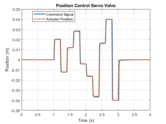
This example shows how to model, parameterize, and test a position control servo valve with a closed loop control. When you run the model, it generates a comparison plot between the commanded and the achieved position in the actuator with respect to the time. A position control servo valve provides a precise and fast control of the position in the actuator with a very small electrical signal to the torque motor. Aerospace, construction and agricultural equipments manufacturers use these valves for safety critical applications.
Model
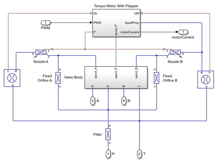
The following figure shows the model of a position control servo valve. Here, connection P is a physical signal port associated with the pressure source. Connection T is physical signal port associated with the reservoir. Connections A and B are physical signal ports associated with the actuator control.

Position Control Servo Valve Subsystem
This subsystem demonstrates how to model the position control servo valve. It includes the flapper nozzle amplifier circuit, the torque motor, and the valve body. The flapper nozzle amplifier circuit includes nozzles and fixed orifices on either side of the flapper as well as a filter. This circuit controls the pressure on both sides of the spool.
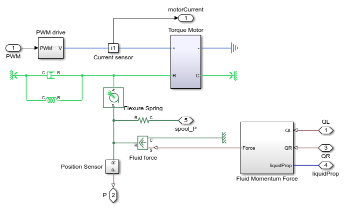
Torque Motor with Flapper Subsystem
This subsystem demonstrates how to model the torque motor and flapper. The flapper transfers the load torque to the torque motor. Forces on the flapper from the flexure tube compression, and nozzle jets result in a load torque.
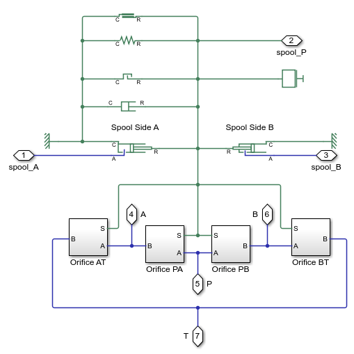
Valve Body Subsystem
This subsystem demonstrates how to model the valve body and spool dynamics including the forces on the spool due to pressure, flexure tube compression, change in flow direction, friction, damping, spool spring compression, and the hard stop. Spool position dictates whether the orifices between the P to A, A to T, P to B, and B to T ports are open or shut.
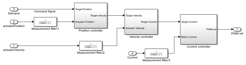
Servo Controller Subsystem
This subsystem demonstrates how to model the servo controller. There are three control loops. The inner loop controls the motor current, the middle loop controls the actuator velocity, and the outer loop controls the actuator position.
Simulation Results from Simscape Logging
This model generates a comparison plot between the commanded and the achieved position in the actuator with respect to the time.