Hydraulic Motor Driven by Load-Sensing Pump
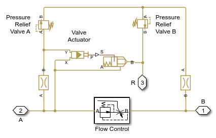
This example shows a circuit that is equipped with a load-sensing velocity regulator installed between the pump and directional valve. Unlike a conventional meter-in velocity control, the load-sensing device automatically adjusts output pressure of the pump in such a way that it equals the sum of the preset pressure drop across the pressure-compensated flow control valve and the pressure induced by load. The pilot-operated pressure-relief valve in the Load-Sensing Velocity Control block is built of the Poppet Valve (IL) and the Pilot Valve Actuator (IL) blocks.
Model

Load-Sensing Velocity Control Subsystem
Simulation Results from Simscape Logging
The plots below show the behavior of the motor as the valve control and load torque are varied.