주요 콘텐츠

Variable Overlapping Orifice (IL)

R2026b

Orifice created by open segments with variable overlap in an isothermal liquid system

  • Variable Overlapping Orifice (IL) block

Libraries:
Simscape / Fluids / Isothermal Liquid / Valves & Orifices / Orifices

Description

The Variable Overlapping Orifice (IL) block models flow through round holes with varying overlapping areas, such as a moving sleeve within a fixed case. The overlapping holes can have different diameters, but additional holes along the spool or sleeve have the same diameter.
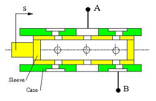
Overlapping Area

The flow rate depends on the variable open area created by overlapping holes in the sleeve and casing. This instantaneous opening area is calculated as:

Aoverlap=r2[cos−1(C2+r2−R22Cr)−(C2+r2−R22Cr)1−(C2+r2−R22Cr)2]+R2[cos−1(C2−r2+R22CR)−(C2−r2+R22CR)1−(C2−r2+R22CR)2],

where:

  • r is the diameter of the smaller hole.

  • R is the diameter of the larger hole.

  • C is the absolute distance between the hole centers, calculated from the physical signal at port S, the instantaneous sleeve position, and the Sleeve position when holes are concentric, S0: C=|S−S0|.

If the holes on the sleeve and casing have the same diameter, the overlap area becomes:

Aoverlap=2r2[cos−1(C2r)−(C2r)1−(C2r)2].

You can maintain numerical robustness in your simulation by adjusting the block Smoothing factor at the nearest and farthest points between hole centers. The block applies a smoothing function to the normalized hole center distance,

C^=(C−R+r)(2r).

The function smoothly saturates the normalized hole center distance between 0 and 1.

For more information, see Numerical Smoothing

Mass Flow Rate Equation

The flow through an orifice pair is calculated from the pressure-area relationship:

m˙=CdAorifice2ρ¯PRloss(1−(AorificeAport)2)Δp[Δp2+Δpcrit2]1/4,

where:

  • Cd is the Discharge coefficient.

  • Aorifice is the area open to flow, Aorifice=Aoverlap+Aleak.

  • A is the Cross-sectional area at ports A and B.

  • ρ¯ is the average fluid density.

Pressure loss describes the reduction of pressure in the valve due to a decrease in area. The pressure loss term, PRloss is calculated as:

PRloss=1−(AoverlappingAport)2(1−Cd2)−CdAoverlappingAport1−(AoverlappingAport)2(1−Cd2)+CdAoverlappingAport.

Pressure recovery describes the positive pressure change in the valve due to an increase in area. If you do not wish to capture this increase in pressure, set Pressure recovery to Off. In this case, PRloss is 1.

The critical pressure difference, Δpcrit, is the pressure differential associated with the Critical Reynolds number, Recrit, the flow regime transition point between laminar and turbulent flow:

Δpcrit=πρ¯8Aoverlapping(νRecritCd)2.

Ports

Conserving

expand all

Entry or exit point to the orifice.

Programmatic Use

Port: A

Entry or exit point to the orifice.

Programmatic Use

Port: B

Input

expand all

Sleeve position with respect to the case, in m.

Programmatic Use

Port: S

Parameters

expand all

Diameter of the hole in the moving element.

Programmatic Use

Parameter: diameter_sleeve

Diameter of hole in the fixed element.

Programmatic Use

Parameter: diameter_case

Moving element position when hole centers are aligned. This parameter is used to the determine instantaneous overlap of the moving and stationary holes during simulation by comparison with the signal received at port S.

Programmatic Use

Parameter: S0

Number of overlapping orifices, in pairs. The sleeve-case pairs do not need to be aligned in the physical hardware being modeled.

Programmatic Use

Parameter: num_pair

Sum of all gaps when the valve is in the fully closed position. Any area smaller than this value is maintained at the specified leakage area. This contributes to numerical stability by maintaining continuity in the flow.

Programmatic Use

Parameter: area_leak

Areas at the entry and exit ports A and B, which are used in the pressure-flow rate equation that determines the mass flow rate through the orifice.

Programmatic Use

Parameter: area

Correction factor that accounts for discharge losses in theoretical flows.

Programmatic Use

Parameter: Cd

Upper Reynolds number limit for laminar flow through the orifice.

Programmatic Use

Parameter: Re_c

Continuous smoothing factor that introduces a layer of gradual change to the flow response when the valve is in near-open or near-closed positions. Set this value to a nonzero value less than one to increase the stability of your simulation in these regimes.

Programmatic Use

Parameter: smoothing_factor

Whether to account for pressure increase when fluid flows from a region of smaller cross-sectional area to a region of larger cross-sectional area.

Programmatic Use

Parameter: pressure_recovery
Values: "true" | "false"

Extended Capabilities

expand all

C/C++ Code Generation
Generate C and C++ code using Simulink® Coder™.

Version History

Introduced in R2020a