Shuttle Valve (IL)
R2026bOne-way switching valve in an isothermal liquid system
Shuttle Valve (IL) block

To add a block to a model, double-click the canvas and start typing the block name. Then, select the block from the list.
Libraries:
Simscape /
Fluids /
Isothermal Liquid /
Valves & Orifices /
Directional Control Valves
Description
The Shuttle Valve (IL) block models a one-way pressure control valve or switching component in an isothermal liquid network. Flow through the valve travels from port A or port A1 to port B. When the pressure differential between A and A1, pAA1, is above a specified threshold pressure, the path between ports A and B is open to flow and the port at A1 closes. The path fully changes when the pressure reaches the value of the Pressure at which A-B is fully open parameter. When pAA1 falls below the threshold pressure, the flow inlet switches to port A1.
Mass Flow Rate Equation
Mass is conserved through the valve
There is no flow between ports A and A1.
The mass flow rate through the valve is
where:
Cd is the value of the Discharge coefficient parameter.
Avalve is the valve open area, either between ports A and B or ports A1 and B.
Aport is the value of the Cross-sectional area at ports A and B parameter.
is the average fluid density.
Δp is the valve pressure difference. Depending on the flow path through the valve, this is either pA – pB, pA1 – pB, or the normalized pressure when switching between the two inlet ports, , defined below.
The critical pressure difference, Δpcrit, is the pressure differential associated with the Critical Reynolds number, Recrit, and is also dependent on the flow path through the valve:
The critical Reynolds number is the flow regime transition point between laminar and turbulent flow.
Pressure loss describes the reduction of pressure in the valve due to a decrease in area, and can change if different valve flow paths have different areas. PRloss is calculated as:
Pressure recovery describes the positive pressure change in the valve
due to an increase in area. If you do not want to capture this increase in pressure,
set the Pressure recovery to Off. In
this case, PRloss is 1.
The opening area, Avalve, is also impacted by the valve opening dynamics.
Opening Parameterization
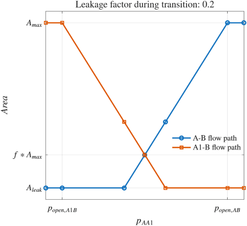
The linear parameterization of the valve area depends on the flow path through the valve. The dynamic area is based on a normally closed path between ports A and B,
where f is the value of the Leakage factor during transition parameter.
The normalized pressure, , is
when pAA1 is between the values of the Pressure at which A1-B is fully open and Pressure at which A-B is fully open parameters. The block saturates the normalized pressure between 0 and 1.
If pAA1 is below the value of the Pressure at which A1-B is fully open parameter, is 0.
If pAA1 is above the value of the Pressure at which A-B is fully open parameter, is 1.
When the valve inlet switches from port A to port A1, the valve opening area is:
The flow path behavior depends on :
When is 0, Avalve,A1B = Amax
When is 0.5, Avalve,A1B = Avalve,AB = f*Amax.
When is 1, Avalve,AB = Amax
This figure shows the valve area for both flow paths across pressure values.
When the valve is in a near-open or near-closed position
in the linear parameterization, you can maintain numerical robustness in your
simulation by adjusting the Smoothing factor parameter. If
the Smoothing factor parameter is nonzero, the block smoothly
saturates the valve area between 0 and 1.
Specifying a nonzero value for the Smoothing factor parameter
provides additional numerical stability when the valve area is changing and in the
near-closed or near-open position. For more information, see Numerical Smoothing.
Opening Dynamics
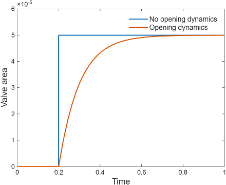
When you select Opening dynamics, the block applies a first-order filter to the valve area based on the Opening time constant parameter, τ. The saturated pressure, sat, becomes the dynamic control pressure, dyn,sat,
When you select Opening dynamics, the valve does not respond to changes instantaneously. This figure shows an example valve area in response to a step in the valve input pressure with and without opening dynamics:
When you clear Opening dynamics, the valve area mirrors the step change in the pressure at the input.
When you select Opening dynamics and set Opening time constant to
0.1
								s
, the valve area asymptotically approaches its limit.
Examples
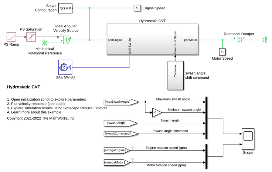
Hydrostatic CVT
Model, parameterize, and test a hydrostatic continuously variable transmission (CVT) with a swash angle shift command. When you run the plot function, it generates a comparison plot between the engine and the achieved rotational velocity in the hydraulic axial piston motor with respect to the time. Construction and agricultural equipment manufacturers use these transmissions.

