Check Valve (TL)
Check valve in a thermal liquid network

Libraries:
Simscape /
Fluids /
Thermal Liquid /
Valves & Orifices /
Directional Control Valves
Description
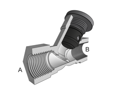
The Check Valve (TL) block models a check valve in the thermal liquid domain. A check valve is a proportional valve that shuts when the pressure difference between its ports drops below a threshold called the cracking pressure. Check valves are common in backflow prevention devices, such as those used in public water supply networks, where contaminated water downstream of a water main must not be allowed to return upstream. The block does not assume a specific valve shutoff mechanism such as a ball, disc, or diaphragm. The allowed direction of flow is always from port A to port B.
The valve cracks open when the pressure drop across the valve rises above the specified cracking pressure. When the pressure drop reaches the maximum value specified in the block, the valve is fully open and its opening area no longer increases with pressure. The flow rate through the valve is never truly zero because a small leakage area remains when the pressure falls below the cracking pressure.
Area vs. Pressure Parameterizations
You can parameterize the block using linear or tabulated area and pressure data.
When Opening parameterization is Linear -
Area vs. pressure, the valve open area is linearly related to
the opening pressure differential. There are two options for valve control:
When Opening pressure differential is
Pressure differential, the control pressure is the pressure differential between ports A and B. The valve begins to open when Pcontrol meets or exceeds the value of the Cracking pressure differential parameter.When Opening pressure differential is
Pressure at port A, the control pressure is the pressure difference between port A and atmospheric pressure. When Pcontrol meets or exceeds the value of the Cracking pressure (gauge) parameter, the valve begins to open.
The linear parameterization of the valve area is
where the normalized pressure, , is
When the valve is in a near-open or near-closed position, you can maintain numerical robustness in your simulation by adjusting the Smoothing factor parameter. If the Smoothing factor parameter is nonzero, the block smoothly saturates the control pressure between pcracking and pmax. For more information, see Numerical Smoothing.
When you set Opening parameterization to
Tabulated data - Volumetric flow rate vs.
                        pressure
, the block linearly interpolates
Avalve from the curve of the
Opening area vector parameter versus the
Pressure differential vector parameter for a simulated
pressure differential.
For the tabulated data and linear area vs pressure parameterizations, the mass flow rate through the valve is
where:
Cd is the value of the Discharge coefficient parameter.
Avalve is the instantaneous valve open area.
Aport is the value of the Cross-sectional area at ports A and B parameter.
is the average fluid density.
Δp is the valve pressure difference pA – pB.
The critical pressure difference, Δpcrit, is the pressure differential associated with the Critical Reynolds number parameter, Recrit, the flow regime transition point between laminar and turbulent flow:
The pressure loss is the reduction of pressure in the valve due to a decrease in area. PRloss is
The pressure recovery is the positive pressure change in the valve due to an increase in area. If you do not want to capture this increase in pressure, clear the Pressure recovery check box. In this case, PRloss is 1.
Tabulated Volumetric Flow Rate Parameterization
When Opening parameterization is Tabulated data
- Volumetric flow rate vs. pressure, the valve opens according to
the user-provided tabulated data of volumetric flow rate and pressure differential
between ports A and B.
The mass flow rate is
where:
is the average fluid density.
where Cd is the discharge coefficient, Recrit is the critical Reynolds number, and ν is the kinematic viscosity. In this parameterization, Cd and Recrit are fixed at
0.64and150, respectively.
When the block operates in the limits of the tabulated data,
where:
ΔpTLU is the Pressure drop vector parameter.
where TLU is the Volumetric flow rate vector parameter.
When the simulation pressure falls below the first element of the
Pressure drop vector parameter,
K=KLeak ,
where TLU(1) is the first element of the Volumetric flow rate vector parameter.
When the simulation pressure rises above the last element of the
Pressure drop vector parameter,
K=KMax,
where TLU(end) is the last element of the Volumetric flow rate vector parameter.
Mass Balance
Mass is conserved through the valve
where is the mass flow rate at port A or B.
Energy Balance
The valve is an adiabatic component. No heat exchange can occur between the fluid and the wall of the valve. No work is done on or by the fluid as it traverses the valve. With these assumptions, energy can enter and exit the valve only by advection, through ports A and B. By the principle of conservation of energy, the sum of the energy flows through the ports must always equal zero,
where ϕ is the energy flow rate into the valve through ports A or B.
Opening Dynamics
When you select Opening dynamics, the block applies a first-order filter to the valve area based on the Opening time constant parameter, τ. The valve area, Avalve, becomes the dynamic area, Adyn,
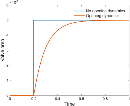
When you select Opening dynamics, the valve does not respond to changes instantaneously. This figure shows an example valve area in response to a step in the valve input pressure with and without opening dynamics:
When you clear Opening dynamics, the valve area mirrors the step change in the pressure at the input.
When you select Opening dynamics and set Opening time constant to
0.1 s, the valve area asymptotically approaches its limit.
Specifying a nonzero value for the Smoothing factor parameter provides additional numerical stability when the valve area is changing and in the near-closed or near-open position. For more information, see Numerical Smoothing.
Faults
To model a fault, in the Faults section, click the Add fault hyperlink next to the fault that you want to model. Use the fault parameters to specify the fault properties. For more information about fault modeling, see Introduction to Simscape Faults.
The Opening area when faulted parameter has three options:
ClosedOpenMaintain at last value
After the fault triggers, the valve remains at the faulted area for the rest of the simulation.
When Opening parameterization is Linear -
Area vs. pressure, the valve area defines the fault options:
Closed— The valve area freezes at the value of the Leakage area parameter.Open— The valve area freezes at the value of the Maximum opening area parameter.Maintain at last value— The valve freezes at the open area when the trigger occurs.
When Opening parameterization is Tabulated
data - Area vs. pressure or Tabulated data -
Volumetric flow rate vs. pressure, the mass flow rate through
the valve defines the fault options:
Closed— The valve freezes at the mass flow rate associated with the first elements of the Volumetric flow rate vector parameter and the Pressure drop vector parametersOpen— The valve freezes at the mass flow rate associated with the last elements of the Volumetric flow rate vector and the Pressure drop vector parametersMaintain at last value— The valve freezes at the mass flow rate and pressure differential when the trigger occurs,
where
Examples

Aircraft Fuel Supply System with Three Tanks
Model an aircraft fuel supply system consisting of three tanks and an engine.