Ports and Resets
Naming HDL Ports
The default names for filter HDL ports are as follows:
| HDL Port | Default Port Name |
|---|---|
| Input port | filter_in |
| Output port | filter_out |
| Clock port | clk |
| Clock enable port | clk_enable |
| Reset port | reset |
| Fractional delay port (Farrow filters only) | filter_fd |
For example, this code shows the default VHDL® declaration for entity filt.
ENTITY filt IS
   PORT( clk               :     IN    std_logic;
         clk_enable        :     IN    std_logic;
         reset             :     IN    std_logic;
         filter_in         :     IN    std_logic_vector (15 DOWNTO 0); -- sfix16_En15
         filter_out        :     OUT   std_logic_vector (15 DOWNTO 0); -- sfix16_En15
         );
END filt;
To change port names,
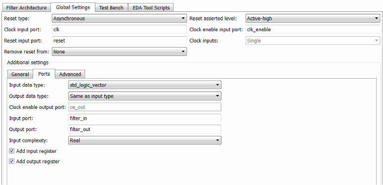
Select the Global Settings tab on the Generate HDL tool.
Select the Ports tab in the Additional settings pane. This figure highlights the port name fields for Input port, Output port, Clock input port, Reset input port, and Clock enable output port.

Enter new character vectors in the port name fields.
Command-Line Alternative: Use the generatehdl function with the properties InputPort, OutputPort, ClockInputPort, ClockEnableInputPort,
and ResetInputPort to change the
names of the filter ports in the generated HDL code.
Specifying the HDL Data Type for Data Ports
By default, filter input and output data ports have data type
std_logic_vector in VHDL and type wire in Verilog®. If you are generating VHDL code, alternatively, you can specify
signed/unsigned, and for output data ports, Same
as input data type. The coder applies type SIGNED or
UNSIGNED based on the data type specified in the filter design.
To change the VHDL data type setting for the input and output data ports,
Select the Global Settings tab on the Generate HDL tool.
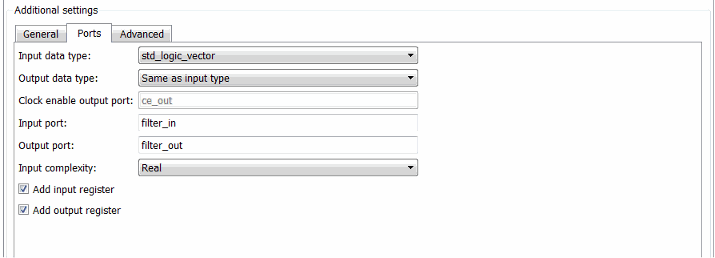
Select the Ports tab in the Additional settings pane.
Select a data type from the Input data type or Output data type menu identified in this figure.
By default, the output data type is the same as the input data type.
The type for Verilog ports is
wire, and cannot be changed.
Note
The setting of Input data type does not apply to double-precision input, which is generated as type
REALfor VHDL andwire[63:0]for Verilog.
Command-Line Alternative: Use the generatehdl function with the properties InputType and OutputType to change the
VHDL data type for the input and output ports.
Selecting Asynchronous or Synchronous Reset Logic
By default, generated HDL code for registers uses asynchronous reset logic. Select asynchronous or synchronous reset logic depending on the type of device you are designing (for example, FPGA or ASIC) and preference.
This code fragment illustrates the use of asynchronous resets. The process block does not check for an active clock before performing a reset.
delay_pipeline_process : PROCESS (clk, reset)
BEGIN
  IF reset = '1' THEN
    delay_pipeline (0 To 50) <= (OTHERS => (OTHERS => '0'));
  ELSIF clk'event AND clk = '1' THEN
    IF clk_enable = '1' THEN
      delay_pipeline(0) <= signed(filter_in);
      delay_pipeline(1 TO 50) <= delay_pipeline(0 TO 49);
    END IF;
  END IF;
END PROCESS delay_pipeline_process;
To change the reset type to synchronous, select Synchronous
from the Reset type menu in the Global settings
pane of the Generate HDL tool.

Code for a synchronous reset follows. This process block checks for a clock event, the rising edge, before performing a reset.
delay_pipeline_process : PROCESS (clk, reset)
BEGIN
  IF rising_edge(clk) THEN
    IF reset = '1' THEN
      delay_pipeline (0 To 50) <= (OTHERS => (OTHERS => '0'));
    ELSIF clk_enable = '1' THEN
      delay_pipeline(0) <= signed(filter_in);
      delay_pipeline(1 TO 50) <= delay_pipeline(0 TO 49);
    END IF;
  END IF;
END PROCESS delay_pipeline_process;
Command-Line Alternative: Use the generatehdl function with the property ResetType to set the reset style
for the registers in the generated HDL code.
Setting the Asserted Level for the Reset Input Signal
The asserted level for the reset input signal determines whether that signal must be
driven to active high (1) or active low (0) for registers to be reset in the filter design.
By default, the coder sets the asserted level to active high. For example, this code
fragment checks whether reset is active high before populating the
delay_pipeline register:
Delay_Pipeline_Process : PROCESS (clk, reset)
BEGIN
  IF reset = '1' THEN
    delay_pipeline(0 TO 50) <= (OTHERS => (OTHERS => '0'));
.
.
.
To change the setting to active low, select Active-low from
the Reset asserted level menu in the Global
settings pane of the Generate HDL tool.

With this change, the IF statement in the preceding generated code
changes to
IF reset = '0' THEN
Note
The Reset asserted level setting also determines the reset level for test bench reset input signals.
Command-Line Alternative: Use the generatehdl function with the property ResetAssertedLevel to
set the asserted level for the reset input signal.
Suppressing Generation of Reset Logic
For some FPGA applications, it is desirable to avoid generation of resets. The Remove reset from option in the Global settings pane of the Generate HDL tool lets you suppress generation of resets from shift registers.
To suppress generation of resets from shift registers, select Shift
register from the Remove reset from pull-down menu in
the Global settings pane of the Generate HDL tool.

If you do not want to suppress generation of resets from shift registers, leave
Remove reset from set to its default, which is
None.
Command-Line Alternative: Use the generatehdl function with the property RemoveResetFrom to suppress
generation of resets from shift registers.
