Generate Simulink Model from CORDIC Atan2 Verilog Code
This example shows how you can import a file containing Verilog® code and generate the corresponding Simulink® model by using the importhdl function. importhdl imports and parses the specified Verilog files to generate the corresponding Simulink model. The Verilog code in this example contains a CORDIC atan2 algorithm.
CORDIC 2-Argument Arctangent (atan2) Verilog Design
This Verilog input file implements a CORDIC atan2 algorithm.
cordic_atan2_verilog_file = 'cordic_atan2.v';
type(cordic_atan2_verilog_file);
`timescale 1ns / 1ps

module cordic_atan2(
    input clk,                      // clock
    input reset,                    // reset to the system
    input enable,                   // enable
    input signed [15:0] x_in,       // Input x value
    input signed [15:0] y_in,       // Input Y value
    output reg signed [15:0] theta  // Input theta value
);

// Pipeline the input values
reg signed [17:0]x_in_d; reg signed [17:0]y_in_d;
always @(posedge clk)
begin
    if(reset)    begin
        x_in_d <={18{1'b0}};
        y_in_d <={18{1'b0}};
    end else if(enable) begin
        // extend the input values for intermediate calculations
        x_in_d <= {{2{x_in[15]}},x_in};
        y_in_d <= {{2{y_in[15]}},y_in};
    end
end
// pre quad correction logic
reg x_qaud_adjust;  reg y_qaud_adjust;
reg y_non_zero;  reg signed [17:0]x_pre_quad_out;
reg signed [17:0]y_pre_quad_out;

always @(posedge clk)begin
    if(reset)begin
        x_pre_quad_out <= {18{1'b0}};
        y_pre_quad_out <= {18{1'b0}};
        x_qaud_adjust  <= 1'b0;
        y_qaud_adjust  <= 1'b0;
        y_non_zero     <=1'b0;
    end
    else if(enable)begin
        if(x_in_d[17] == 1'b1)begin
            x_pre_quad_out <= -x_in_d;
            x_qaud_adjust  <= 1'b1;
        end
        else begin
            x_pre_quad_out <= x_in_d;
            x_qaud_adjust  <= 1'b0;
        end
        if(y_in_d[17] == 1'b1)begin
            y_pre_quad_out <= -y_in_d;
            y_qaud_adjust  <= 1'b1;
            y_non_zero     <=1'b1;
        end
        else begin
            y_pre_quad_out <= y_in_d;
            y_qaud_adjust  <= 1'b0;
            y_non_zero     <= |y_in_d; // reduction or for test non zero or not
        end
    end
end

//LOOKUP TABLE FOR THE ANGLES
wire signed [15:0]LUT[0:14];
wire signed [17:0]x_k[0:15];
wire signed [17:0]y_k[0:15];
wire signed [17:0]z_k[0:15];
wire signed [15:0]theta_temp;
parameter PI = 16'sh6488;

assign LUT[0]  = 16'h1922;
assign LUT[1]  = 16'h0Ed6;
assign LUT[2]  = 16'h07D7;
assign LUT[3]  = 16'h03FB;
assign LUT[4]  = 16'h01FF;
assign LUT[5]  = 16'h0100;
assign LUT[6]  = 16'h0080;
assign LUT[7]  = 16'h0040;
assign LUT[8]  = 16'h0020;
assign LUT[9]  = 16'h0010;
assign LUT[10] = 16'h0008;
assign LUT[11] = 16'h0004;
assign LUT[12] = 16'h0002;
assign LUT[13] = 16'h0001;
assign LUT[14] = 16'h0000;

assign x_k[0]  = x_pre_quad_out;
assign y_k[0]  = y_pre_quad_out;

wire  signed [17:0]theta_temp0;
assign theta_temp0 = z_k[15];
assign theta_temp  = theta_temp0[15:0];
assign z_k[0] = 18'd0;

//cordic iterator
genvar  i;
generate
for (i = 0; i<15; i =i+1)
begin
    Kernel cordic_iterator (.clk (clk),
        .reset(reset),
        .enable  (enable ),
        .itr_num(i),
        .x_in(x_k[i]),
        .y_in(y_k[i]),
        .z_in(z_k[i]),
        .lut_constant(LUT[i]),
        .x_out(x_k[i+1]),
        .y_out(y_k[i+1]),
        .z_out(z_k[i+1])
    );
end
endgenerate

// matching delays for the control signls of the pre quadrant correction logic
reg x_qaud_adjust_match_delay[0:14];
reg y_qaud_adjust_match_delay[0:14];
reg y_non_zero_match_delay[0:14];
integer k;
always @(posedge clk)begin
    if(reset)begin
        x_qaud_adjust_match_delay[0] <= 1'b0; y_qaud_adjust_match_delay[0] <= 1'b0;
        y_non_zero_match_delay   [0] <= 1'b0; x_qaud_adjust_match_delay[1] <= 1'b0;
        y_qaud_adjust_match_delay[1] <= 1'b0; y_non_zero_match_delay   [1] <= 1'b0;
        x_qaud_adjust_match_delay[2] <= 1'b0; y_qaud_adjust_match_delay[2] <= 1'b0;
        y_non_zero_match_delay   [2] <= 1'b0; x_qaud_adjust_match_delay[3] <= 1'b0;
        y_qaud_adjust_match_delay[3] <= 1'b0; y_non_zero_match_delay   [3] <= 1'b0;
        x_qaud_adjust_match_delay[4] <= 1'b0; y_qaud_adjust_match_delay[4] <= 1'b0;
        y_non_zero_match_delay   [4] <= 1'b0; x_qaud_adjust_match_delay[5] <= 1'b0;
        y_qaud_adjust_match_delay[5] <= 1'b0; y_non_zero_match_delay   [5] <= 1'b0;
        x_qaud_adjust_match_delay[6] <= 1'b0; y_qaud_adjust_match_delay[6] <= 1'b0;
        y_non_zero_match_delay   [6] <= 1'b0; x_qaud_adjust_match_delay[7] <= 1'b0;
        y_qaud_adjust_match_delay[7] <= 1'b0; y_non_zero_match_delay   [7] <= 1'b0;
        x_qaud_adjust_match_delay[8] <= 1'b0; y_qaud_adjust_match_delay[8] <= 1'b0;
        y_non_zero_match_delay   [8] <= 1'b0; x_qaud_adjust_match_delay[9] <= 1'b0;
        y_qaud_adjust_match_delay[9] <= 1'b0; y_non_zero_match_delay   [9] <= 1'b0;
        x_qaud_adjust_match_delay[10] <= 1'b0; y_qaud_adjust_match_delay[10] <= 1'b0;
        y_non_zero_match_delay   [10] <= 1'b0; x_qaud_adjust_match_delay[11] <= 1'b0;
        y_qaud_adjust_match_delay[11] <= 1'b0; y_non_zero_match_delay   [11] <= 1'b0;
        x_qaud_adjust_match_delay[12] <= 1'b0; y_qaud_adjust_match_delay[12] <= 1'b0;
        y_non_zero_match_delay   [12] <= 1'b0; x_qaud_adjust_match_delay[13] <= 1'b0;
        y_qaud_adjust_match_delay[13] <= 1'b0; y_non_zero_match_delay   [13] <= 1'b0;
        x_qaud_adjust_match_delay[14] <= 1'b0; y_qaud_adjust_match_delay[14] <= 1'b0;
        y_non_zero_match_delay   [14] <= 1'b0;
    end
    else if(enable) begin
        x_qaud_adjust_match_delay[0] <=x_qaud_adjust;
        y_qaud_adjust_match_delay[0] <=y_qaud_adjust;
        y_non_zero_match_delay[0]    <=y_non_zero;
        for(k =0; k <14 ;k = k+1)begin
            x_qaud_adjust_match_delay[k+1] <=  x_qaud_adjust_match_delay[k];
            y_qaud_adjust_match_delay[k+1] <= y_qaud_adjust_match_delay[k];
            y_non_zero_match_delay[k+1] <= y_non_zero_match_delay[k];
        end
    end
end
// post quadrant correction logic

always @(posedge clk) begin
    if(reset)
        theta<=16'd0;
    else if(enable)begin
        if(y_non_zero_match_delay[14])begin
            if(x_qaud_adjust_match_delay[14])begin
                if(y_qaud_adjust_match_delay[14])
                    theta <=theta_temp -PI;
                else
                    theta <=PI -theta_temp;
            end
            else begin
                if(y_qaud_adjust_match_delay[14])
                    theta <= -theta_temp;
                else
                    theta <= theta_temp;
            end
        end
        else if(x_qaud_adjust_match_delay[14])begin
            theta <= PI;
        end
        else begin
            theta <= 16'd0;
        end
    end
end

endmodule

module  Kernel(
    input clk,
    input reset,
    input enable,
    input signed [17:0]x_in,
    input signed [17:0]y_in,
    input signed [17:0]z_in,
    input [4:0]itr_num,
    input signed [15:0]lut_constant,
    output reg signed [17:0]x_out,
    output reg signed [17:0]y_out,
    output reg signed [17:0]z_out);

wire signed [17:0] lut_constant_signExtension = {{2{lut_constant[15]}},lut_constant};

always @(posedge clk)begin
    if(reset)begin
        x_out <={18{1'b0}};
        y_out <={18{1'b0}};
        z_out <= {18{1'b0}};
    end
    else if(enable)begin
        if(y_in[17])begin
            x_out <= x_in -(y_in>>>itr_num);
            y_out <= y_in + (x_in>>>itr_num);
            z_out <= z_in  - lut_constant_signExtension;
        end
        else begin
            x_out <= x_in +(y_in>>>itr_num);
            y_out <= y_in - (x_in>>>itr_num);
            z_out <= z_in  + lut_constant_signExtension;
        end
    end
end

endmodule
This Verilog design contains various commonly used Verilog constructs such as:
Continuous assignments
Always blocks
Conditional Statements
Module instantiation
Generate Constructs
For Loop
Import HDL File Containing CORDIC atan2 Algorithm
To import the Verilog file, specify the file name as an argument to the importhdl function.
importhdl(cordic_atan2_verilog_file);
### Parsing <a href="matlab:edit('cordic_atan2.v')">cordic_atan2.v</a>.
### Top Module name: 'cordic_atan2'.
### Identified ClkName::clk.
### Identified RstName::reset.
### Identified ClkEnbName::enable.
Warning: Unused signals detected in the Demux block created for vector index signal 'x_k'. A Demux block created for a vector index signal has all possible output signals based on the size and dimensions provided.
Warning: Unused signals detected in the Demux block created for vector index signal 'y_k'. A Demux block created for a vector index signal has all possible output signals based on the size and dimensions provided.
### Hdl Import parsing done.
### Removing unconnected components.
### Unconnected components detected when importing the HDL code. These components are removed from the generated Simulink model.
### Creating Target model cordic_atan2
### Begin model generation 'cordic_atan2'...
### Rendering DUT with optimization related changes (IO, Area, Pipelining)...
### Start Layout...
### Working on hierarchy at ---> 'cordic_atan2'.
### Laying out components.
### Working on hierarchy at ---> 'cordic_atan2/cordic_atan2'.
### Laying out components.
### Working on hierarchy at ---> 'cordic_atan2/cordic_atan2/cordic_iterator'.
### Laying out components.
### Drawing block edges...
### Working on hierarchy at ---> 'cordic_atan2/cordic_atan2/cordic_iterator1'.
### Laying out components.
### Drawing block edges...
### Working on hierarchy at ---> 'cordic_atan2/cordic_atan2/cordic_iterator10'.
### Laying out components.
### Drawing block edges...
### Working on hierarchy at ---> 'cordic_atan2/cordic_atan2/cordic_iterator11'.
### Laying out components.
### Drawing block edges...
### Working on hierarchy at ---> 'cordic_atan2/cordic_atan2/cordic_iterator12'.
### Laying out components.
### Drawing block edges...
### Working on hierarchy at ---> 'cordic_atan2/cordic_atan2/cordic_iterator13'.
### Laying out components.
### Drawing block edges...
### Working on hierarchy at ---> 'cordic_atan2/cordic_atan2/cordic_iterator14'.
### Laying out components.
### Drawing block edges...
### Working on hierarchy at ---> 'cordic_atan2/cordic_atan2/cordic_iterator2'.
### Laying out components.
### Drawing block edges...
### Working on hierarchy at ---> 'cordic_atan2/cordic_atan2/cordic_iterator3'.
### Laying out components.
### Drawing block edges...
### Working on hierarchy at ---> 'cordic_atan2/cordic_atan2/cordic_iterator4'.
### Laying out components.
### Drawing block edges...
### Working on hierarchy at ---> 'cordic_atan2/cordic_atan2/cordic_iterator5'.
### Laying out components.
### Drawing block edges...
### Working on hierarchy at ---> 'cordic_atan2/cordic_atan2/cordic_iterator6'.
### Laying out components.
### Drawing block edges...
### Working on hierarchy at ---> 'cordic_atan2/cordic_atan2/cordic_iterator7'.
### Laying out components.
### Drawing block edges...
### Working on hierarchy at ---> 'cordic_atan2/cordic_atan2/cordic_iterator8'.
### Laying out components.
### Drawing block edges...
### Working on hierarchy at ---> 'cordic_atan2/cordic_atan2/cordic_iterator9'.
### Laying out components.
### Drawing block edges...
### Drawing block edges...
### Drawing block edges...
### Model generation complete.
### Setting model parameters.
### Generated model file /tmp/Bdoc26a_3233028_1593697/tpd02adb13/hdlcoder-ex38650911/hdlimport/cordic_atan2/cordic_atan2.slx.
### Importhdl completed.
importhdl parses the input file and displays messages of the import process in the MATLAB™ Command Window. The import provides a link to the generated Simulink model cordic_atan2.slx. The generated model uses the same name as the top module in the input Verilog file.
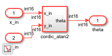
Examine Generated Simulink Model
To open the generated Simulink model, click the link in the Command Window. The model is saved in the hdlimport/cordic_atan2 path relative to the current folder. You can simulate the model and observe the simulation results.
open_system('hdlimport/cordic_atan2/cordic_atan2')
Simulink.BlockDiagram.arrangeSystem('cordic_atan2')
set_param('cordic_atan2', 'UnconnectedOutputMsg', 'None');
sim('hdlimport/cordic_atan2/cordic_atan2.slx');
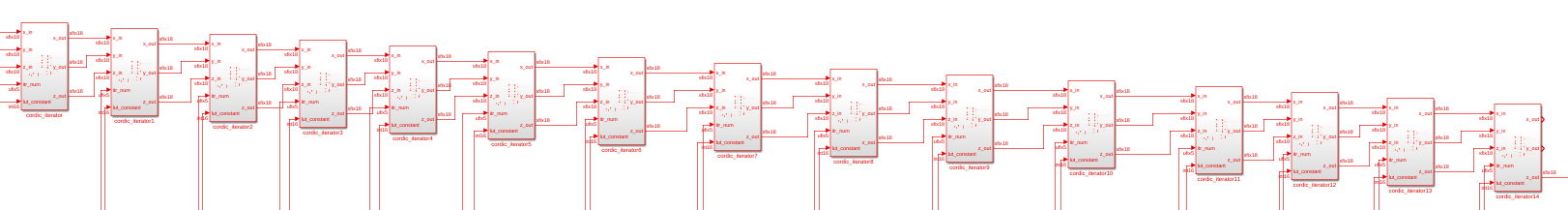
Generated Module instances
The Verilog code instantiates 15 kernel modules by using the generate construct. In the generated Simulink model, 15 kernel modules are seen.
generate
    for (i = 0; i<15; i =i+1)
    begin
        Kernel cordic_iterator (.clk(clk),
                                .reset(reset),
                                .enable(enable),
                                .itr_num(i),
                                .x_in(x_k[i]),
                                .y_in(y_k[i]),
                                .z_in(z_k[i]),
                                .lut_constant(LUT[i]),
                                .x_out(x_k[i+1]),
                                .y_out(y_k[i+1]),
                                .z_out(z_k[i+1]));
    end
endgenerate
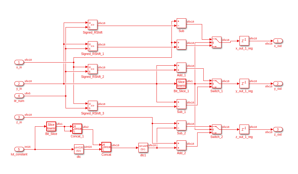
Simulink model for the Kernel Module
module  Kernel(
    input clk,
    input reset,
    input enable,
    input signed [17:0]x_in,
    input signed [17:0]y_in,
    input signed [17:0]z_in,
    input [4:0]itr_num,
    input signed [15:0]lut_constant,
    output reg signed [17:0]x_out,
    output reg signed [17:0]y_out,
    output reg signed [17:0]z_out);
wire signed [17:0] lut_constant_signExtension = {{2{lut_constant[15]}},lut_constant};
always @(posedge clk)begin
      if(reset)begin
         x_out <={18{1'b0}};
         y_out <={18{1'b0}};
         z_out <= {18{1'b0}};
      end
    else if(enable)begin
        if(y_in[17])begin
            x_out <= x_in -(y_in>>>itr_num);
            y_out <= y_in + (x_in>>>itr_num);
            z_out <= z_in  - lut_constant_signExtension;
        end
        else begin
            x_out <= x_in +(y_in>>>itr_num);
            y_out <= y_in - (x_in>>>itr_num);
            z_out <= z_in  + lut_constant_signExtension;
          end
      end
 end
endmodule