Generate HDL Code for Simscape Models by Using Dynamic Switch Approximation
This example shows how to generate HDL code for a Simscape™ model by using dynamic switch approximation method [1] and deploy onto an FPGA board.
Simscape Model with Dynamic Switch Approximation
You can use the dynamic switch approximation method to convert the Simscape™ three-phase permanent magnet synchronous motor (PMSM) model to an optimized HDL implementation model for HDL code generation and synthesis.
In this example, you learn how to:
Generate an optimized model by using the
sschdl.generateOptimizedModelfunction. This function replaces the Simscape switches in your model with their dynamic equivalents.Automatically tune the parameter values for the dynamic switches in the optimized model.
Generate an HDL implementation model by using the Simscape HDL Workflow Advisor, generate the HDL code, and synthesize the results.
You can then deploy the generated HDL code onto a Speedgoat® FPGA I/O module.
The dynamic switch approximation method supports all local solvers. This method provides an improved FPGA sample rate, reduced resource utilization, and dead time stability, and prevents validation errors. For more information on validation errors, see Troubleshoot Validation Errors in Simscape Hardware-in-the-Loop Workflow.
Set Up Synthesis Tool Path
To synthesize the generated HDL code, before you use HDL Coder™ to generate code, set up your synthesis tool path. For example, if your synthesis tool is Xilinx® Vivado®, install the latest version of Xilinx Vivado as shown in HDL Language Support and Supported Third-Party Tools and Hardware.
Then, set the tool path to the installed Xilinx Vivado executable by using the hdlsetuptoolpath function. For example, this command sets the synthesis tool path to point to your installed Vivado® Design Suite 2024.1 batch file:
hdlsetuptoolpath("ToolName","Xilinx Vivado",...
"ToolPath","C:\Xilinx\Vivado\2024.1\bin\vivado.bat")
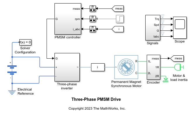
Three-Phase PMSM Drive
The model used in this example contains a three-phase PMSM in wye-wound configuration and a three-phase inverter. This model uses field-oriented control (FOC) to control the speed of the three-phase PMSM. The PMSM is a nonlinear block in the model. The Three-phase inverter subsystem has the switching elements as the ideal insulated-gate bipolar transistor IGBT (Ideal, Switching) (Simscape Electrical) (with an integral protection diode) and is connected to a battery. These Simscape switches are replaced by their dynamic equivalents in the generated optimized model by using dynamic switch approximation. This model uses the Partitioning solver as a local solver and runs at a time step of 2 μs with a switching frequency of 2 kHz.
Open the model at the MATLAB® command prompt.
open_system("sschdlexThreePhasePMSMDrive")
To see the waveforms, simulate the model.
sim("sschdlexThreePhasePMSMDrive")
open_system("sschdlexThreePhasePMSMDrive/Scope")

Close the Scope.
close_system("sschdlexThreePhasePMSMDrive/Scope")
PMSM Model with Dynamic Switch Approximation
You can modify the sschdlexThreePhasePMSMDrive model for FPGA deployment by using dynamic switch approximation. The sschdl.generateOptimizedModel function replaces the Simscape switches (IGBTs-with an integral protection diode) with their dynamic equivalents from the Dynamic Switch Library (SimscapeFPGAHIL_lib). The library has the IGBTs and diodes optimized for HDL code generation (Simscape HIL simulation). You can open the library from the MATLAB® Command Window.
To open this library, enter:
SimscapeFPGAHIL_lib
The library window contains the Dynamic Switch Models subsystem. This subsystem contains dynamic approximation of the piecewise linear switching elements.

Generate Optimized Model and Tune Dynamic Switch Parameter Values
To optimize the model for FPGA deployment, run the sschdl.generateOptimizedMode function at the MATLAB command prompt.
generatedModel = sschdl.generateOptimizedModel("sschdlexThreePhasePMSMDrive",ReplaceSwitches=true,ReplacePMSM=false);
The following blocks have been replaced:
'sschdlexThreePhasePMSMDrive/Three-phase inverter/IGBT A(H)'
'sschdlexThreePhasePMSMDrive/Three-phase inverter/IGBT A(L)'
'sschdlexThreePhasePMSMDrive/Three-phase inverter/IGBT B(H)'
'sschdlexThreePhasePMSMDrive/Three-phase inverter/IGBT B(L)'
'sschdlexThreePhasePMSMDrive/Three-phase inverter/IGBT C(H)'
'sschdlexThreePhasePMSMDrive/Three-phase inverter/IGBT C(L)'

Saving sschdlexThreePhasePMSMDrive as sschdlexThreePhasePMSMDrive_generated and replacing switch and converter blocks with equivalent FPGA HIL supported blocks.

The generated optimized model for the three-phase PMSM drive model is saved as sschdlexThreePhasePMSMDrive_generated. In this model, the Three-phase inverter subsystem contains the replaced IGBT subsystem blocks.
If you have a license for the Simulink® Design Optimization™ toolbox, you can fine-tune the parameter values for the dynamic switches while generating the optimized model. To enable fine-tuning, run this command at the MATLAB command prompt:
generatedModel = sschdl.generateOptimizedModel("sschdlexThreePhasePMSMDrive",ReplaceSwitches=true,...
ReplacePMSM=false,FineTune=true);
The values are updated in the generated optimized model when the optimization stops in the MATLAB® Command Window. You can verify the tuned parameter values using the sschdlexThreePhasePMSMDrive_tuned model. Open the tuned optimized model.
open_system("sschdlexThreePhasePMSMDrive_tuned");
Open the generated optimized model.
open_system("sschdlexThreePhasePMSMDrive_generated")
When you simulate this model, the results of this model and the original Simscape model are same. To see how the model works, simulate the model.
sim("sschdlexThreePhasePMSMDrive_generated")
open_system("sschdlexThreePhasePMSMDrive_generated/Scope")
To open the modified subsystem of the generated optimized model, enter:
open_system("sschdlexThreePhasePMSMDrive_generated")
open_system("sschdlexThreePhasePMSMDrive_generated/Three-phase inverter")

Double-click the IGBT subsystem block. It consists of a diode and an IGBT (ideal_switch). You can update the values of its parameters.
The Conductance ( ) parameter specifies the conductance of the resistor in
 Dynamic Switch Models. This value is different from the off-state conductance,  , of an IGBT (Ideal, Switching) (Simscape Electrical) when it is used for switching applications. The Time scaling (
 ) parameter scales the speed of the switching device response with respect to time.
For the IGBT (ideal_switch) block, the parameter values of:
Forward Voltage is set to
0.8Threshold Voltage is set to
0.5Conductance is set to
2.1246Time scaling is set to
1
Double-click the diode block in the IGBT subsystem to check and update its parameter values. For the diode block, the parameter values of:
Forward Voltage is set to
0.8Conductance is set to
2.1246Time scaling is set to
1
Similarly, update the parameter values for the other IGBT+Diode subsystems. The initial value of as,
 ,
,
where  is the closed circuit current and
  is the open circuit voltage of the switch. For this example, the values of and are approximately 100 A and 47 V, leading to an initial value of 2.12 1/Ohm for .
You can automatically tune the parameter values for dynamic switches after the optimized model generation by using the sschdl.tuneOptimizedModel function. If you have a license for the Simulink® Design Optimization™ toolbox, you can further fine-tune the parameter values.
To enable fine-tuning, run this command at the MATLAB command prompt:
y = sschdl.tuneOptimizedModel("sschdlexThreePhasePMSMDrive",...
optimizedModel="sschdlexThreePhasePMSMDrive_generated",FineTune=true);
Generate HDL Implementation Model
The Simscape HDL Workflow Advisor converts the Simscape plant model to an HDL-compatible implementation model from which you generate HDL code. To generate the HDL implementation model from the optimized model:
1. Open the Simscape HDL Workflow Advisor.
sschdladvisor("sschdlexThreePhasePMSMDrive_generated/Three-phase inverter")
2. In the Implementation model generation task folder, select the Set target task and specify the Synthesis tool as Xilinx Vivado. Specify the Family as Kintex7, Device as xc7k325t, Package as fbg676, and Speed as -1. Right-click the Generate implementation model task, then select Run to Selected Task.
After the task passes, you see a link to the HDL implementation model gmStateSpaceHDL_sschdlexThreePhasePM.
Generate HDL Code from Implementation Model
To modify the configuration parameter values for HDL code generation, enter this command at the MATLAB command prompt.
hdlsetup("gmStateSpaceHDL_sschdlexThreePhasePM")
Open HDL Workflow Advisor
The HDL Workflow Advisor guides you through the tasks required for generating HDL code and an FPGA design process. It provides you with feedback on the results of each task. When you complete the tasks, you have a synthesis result report from your selected synthesis tool. For more information, see HDL Workflow Advisor Tasks.
Open the HDL Workflow Advisor for the HDL Subsystem1 block in the HDL implementation model.
hdladvisor("gmStateSpaceHDL_sschdlexThreePhasePM/HDL Subsystem1")
You can also open the HDL Workflow Advisor from your model window. Right-click the subsystem HDL Subsystem1 and select HDL Workflow Advisor from the list.
Set Target Device and Synthesis Tool
Before you generate HDL code, if you want to deploy the code onto a target platform, specify the synthesis tool.
Open the HDL Workflow Advisor.
Under the Set Target task folder, in the Set Target Device and Synthesis Tool task, the fields are auto-populated if you have specified the target device in Simscape HDL Workflow Advisor while generating HDL implementation model.
In the Set Target Frequency task, the Target Frequency is automatically set to
201.5.Select the task that you want to run and click Run This Task.
Generate HDL Code
To generate HDL code, run the tasks under the HDL Code Generation task folder.
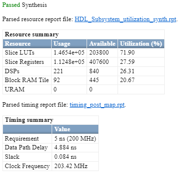
Synthesize Generated HDL Code
HDL Coder synthesizes the HDL code on the target platform and generates area and timing reports for your design based on the target device that you specify. You can run logic synthesis for a specified FPGA device and get the synthesis reports.
In the FPGA Synthesis and Analysis task folder:
Create an FPGA synthesis project for your supported FPGA synthesis tool.
Start supported FPGA synthesis tools to perform synthesis, mapping, and place/route tasks. To run FPGA synthesis, right-click the Run Synthesis task under the Perform Synthesis and P/R folder. This starts Xilinx Vivado and executes the Vivado Synthesis step. You can annotate your original model with critical path information obtained from the synthesis tools.
Deploy Three-Phase PMSM Drive to Speedgoat FPGA I/O Modules
In the HDL implementation model, the HDL Subsystem1 block contains blocks you run on the FPGA. You can run the HDL Workflow Advisor on this subsystem to deploy the HDL algorithm onto FPGA boards in Speedgoat target computers. For an example, see FPGA-Based HIL Deployment of Simscape Model on Speedgoat FPGA I/O Module.
References
[1] Pejovic, P., and D. Maksimovic. “A Method for Fast Time-Domain Simulation of Networks with Switches.” IEEE Transactions on Power Electronics 9, no. 4 (July 1994): 449–56, https://doi.org/10.1109/63.318904.
See Also
Functions
Topics
- Generate and Validate HDL Code for Simscape Model
- Tune Parameter Values for Dynamic Switches in Half-Wave Rectifier Model
- FPGA-Based HIL Deployment of Simscape Model on Speedgoat FPGA I/O Module
- Generate HDL Code for Nonlinear Simscape Models by Using Partitioning Solver
- Simulate Large Time Steps Using Trapezoidal Rule Solver for Real-Time FPGA Deployment
- Generate HDL Code for Simscape Three-Phase PMSM Drive Containing Averaged Switch
- Deploy Simscape DC Motor Model to Speedgoat FPGA IO Module
- Generate Optimized Simscape Three-Phase PMSM Drive Model for Real-Time FPGA HIL Deployment