Generate IP Core for Frame-Based Model with AXI4 Stream Interfaces
This example shows how to leverage the frame to sample optimization from HDL Coder™ to generate a sample-based IP core with AXI4-Stream interfaces from a frame-based Simulink® model. The generated IP core can then be deployed to hardware and verified using live streaming data from MATLAB®.
It is common to model frame-based algorithms in MATLAB and Simulink. This modeling style allows intuitive algorithm designs that process data as entire frames using frame-based operations. However, these operations are not efficient to implement on FPGA/ASIC devices, which typically process large datasets as samples. Thus, frame-based algorithms need manual conversion to their sample-based counterparts before deployment, adding time-consuming and error-prone work to the design process.
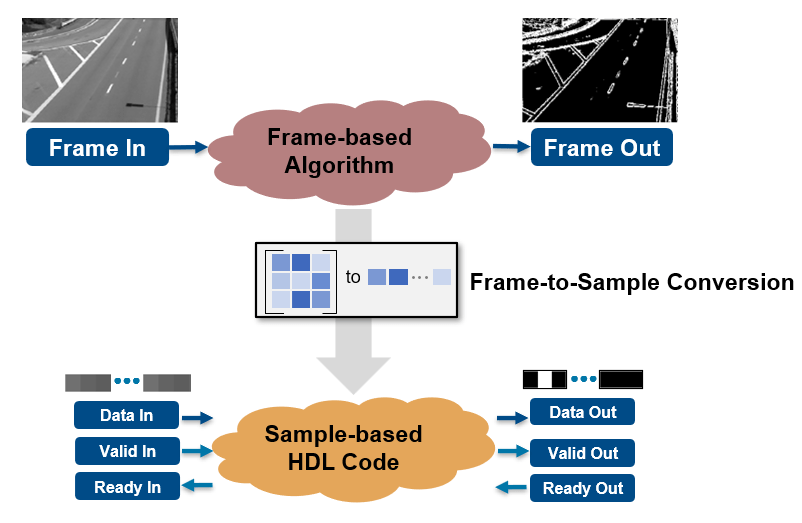
Using the frame to sample optimization, HDL Coder automates the frame to sample conversion process and generates sample-based HDL code for frame-based algorithms modeled using element-wise operations, neighborhood idioms, iterator, and reduction operations. When you use the frame to sample conversion, HDL Coder automatically transforms your frame-based algorithm into a sample-based model with valid and ready control signals and the logic to handle and align the data streams as shown below:
In this example, you:
Model a frame-based edge detection algorithm by using neighborhood processing functions.
Generate an HDL IP core with an AXI4-Stream interface.
Integrate the generated IP core into a reference design with a DMA controller.
Use a simple script to prototype the design running on hardware with live data.
Prerequisites
To run this example, you must have the following software installed and hardware boards setup:
HDL Coder Support Package for AMD® FPGA and SoC Devices
Xilinx Vivado® (To view the supported versions, see HDL Language Support and Supported Third-Party Tools and Hardware)
Xilinx SoC board. This example uses the Xilinx Zynq ZC706 evaluation kit.
MathWorks® firmware image on the SD card of the board. For help with SD card setup, see Guided Hardware Setup for AMD Boards.
Model an Edge Detection Algorithm Using Neighborhood Processing Functions
Open the frame-based edge detection model.
open_system('hdlcoder_tunable_edge_detection')
set_param('hdlcoder_tunable_edge_detection', 'SimulationCommand', 'Update')
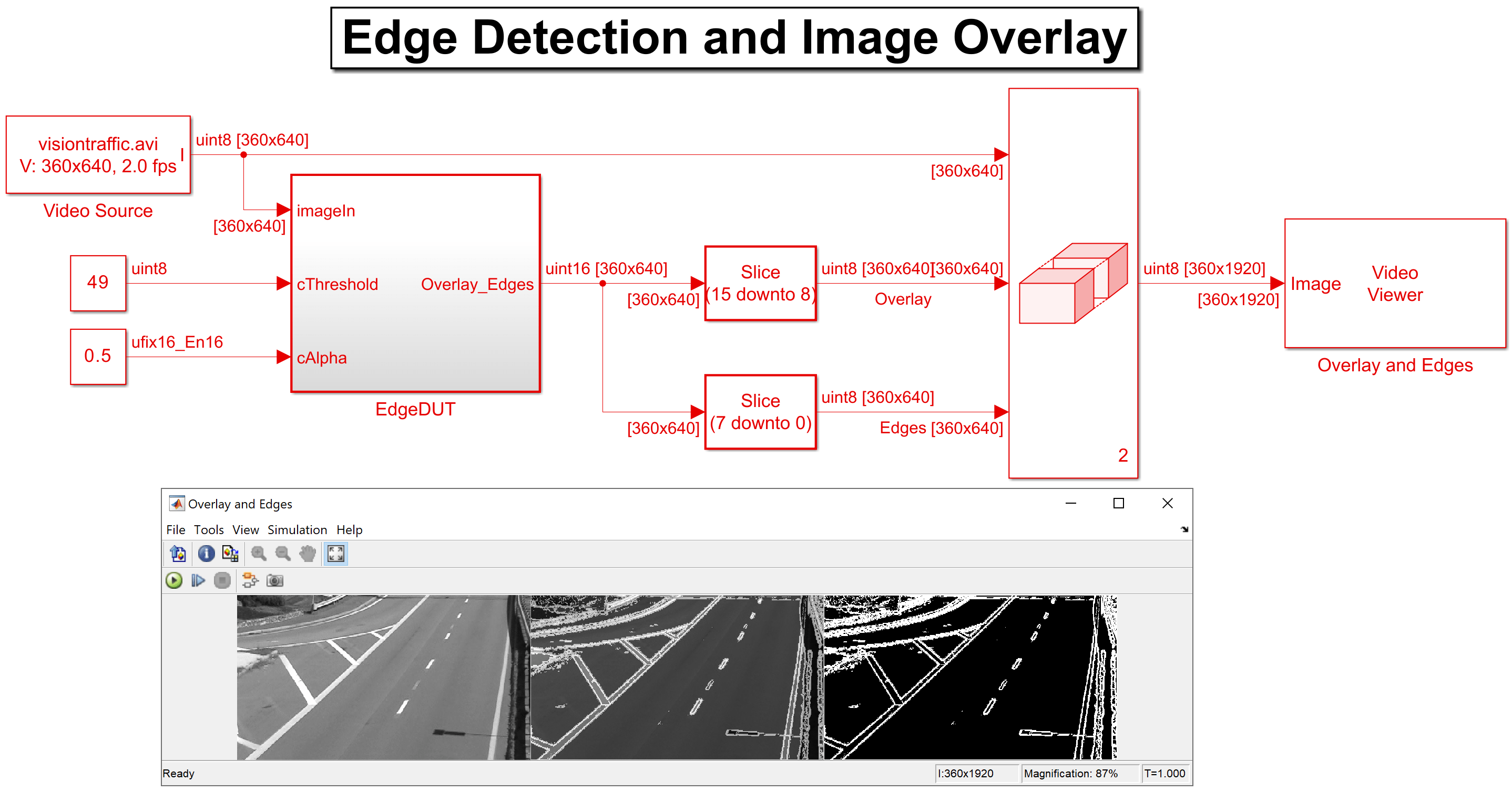
The model consists of the design under test (DUT) and the test bench. The DUT contains a MATLAB® Function block that models a Sobel edge detection algorithm by using the hdl.npufun function. The edge calculation uses scalar input parameters, cThreshold and cAlpha, with the frame input to compute the edge overlay on the original frame input. For more information, see hdl.npufun.
function [O,E]  = edgeDetectionAndOverlay(I, cThreshold, cAlpha)

E = hdl.npufun(@sobel_kernel, [3 3], I,'KernelArg', cThreshold);
O = hdl.npufun(@mix_kernel, [1 1], E, I,'KernelArg', cAlpha);

end

function e = sobel_kernel(in,cThreshold)

u = fi(in);
hGrad = u(1) + fi(2)*u(2) + u(3) - (u(7) + fi(2)*u(8) + u(9));
vGrad = u(1) + fi(2)*u(4) + u(7) - (u(3) + fi(2)*u(6) + u(9));

hGrad = bitshift(hGrad, -3); % Divide by 8
vGrad = bitshift(vGrad, -3); % Divide by 8

thresholdValueSq = fi(cThreshold); % Edge threshold
e = (hGrad*hGrad + vGrad*vGrad) > thresholdValueSq;

end

function O = mix_kernel(E, I, cAlpha)

alpha = fi(cAlpha); % Parameter for combining images
scaleE = E*fi(255,0,8,0);
O = scaleE * (fi(1)-alpha) + I*alpha;

end
You can use the hdl.npufun function for the frame-to-sample conversion to translate the frame-based algorithm into a sample-based algorithm. You can connect the streaming I/O of your sample-based algorithm to a streaming interface. Additionally, you can map the tunable parameters to AXI4-Lite or External Ports.
When you convert this model by using the HDL Coder Workflow Advisor, you generate an AXI4-Stream interface that contains the signals in this image:
Generate HDL IP Core
Generate an IP core from the frame-based DUT by using the HDL Workflow Advisor.
1. Enable the frame-to-sample conversion by entering this command:
hdlset_param('hdlcoder_tunable_edge_detection','FrameToSampleConversion','on');
2. Enable the HDL block property ConvertToSamples for the input image to be streamed (imageIn) using this command:
hdlset_param('hdlcoder_tunable_edge_detection/EdgeDUT/imageIn','ConvertToSamples','on');
3. Set up the Xilinx Vivado synthesis tool path by using the hdlsetuptoolpath command. Use your own Vivado installation path when you run the command.
hdlsetuptoolpath('ToolName','Xilinx Vivado','ToolPath',vivadopath);
4. Open the HDL Coder app. Click the Apps tab, then open HDL Coder. Click the Workflow Advisor button to open the HDL Workflow Advisor.
5. Click 1. Set Target > 1.1. Set Target device and Synthesis Tool, then set Target Workflow to IP Core Generation and Target Platform to Xilinx Zynq ZC706 evaluation kit. If you are targeting a different Xilinx SoC, choose your board from the Target Platform context menu.
6. Click 1.2.Set Target Reference Design, then set Reference design to Default system with AXI4-Stream interface.
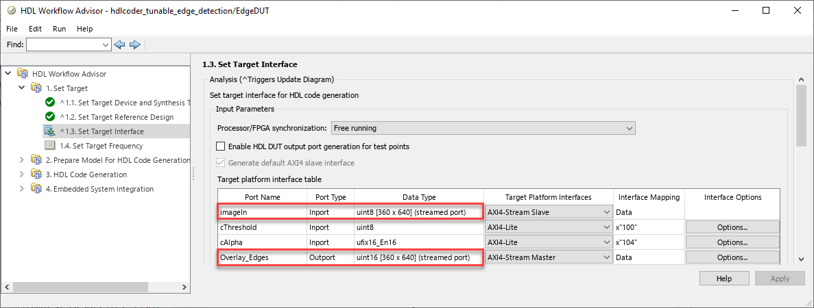
7. Click 1.3.Set Target Interface. The ports of the DUT subsystem are mapped to IP core interfaces. The AXI4-Stream interface communicates in master/slave mode, where the master device sends data to the slave device. For this example, for the input port, imageIn, set Target Platform Interfaces to AXI4-Stream Slave and set the output port, Overlay_Edges, to AXI4-Stream Master. The cells in Data Type column that include streamed port indicate the ports you can map to stream interfaces. Finally, to control the tunable parameters at runtime, set Target Platform Interfaces to AXI4-Lite for the non-streamed kernel inputs, cAlpha and cThreshold.
Click Run This Task.
The AXI4-Stream interface contains data (Data_In, Data_Out) and control signals such as data valid (Valid_In, Valid_Out), back pressure (Ready_In, Ready_Out), and data boundary (TLAST). It is only required to map your frame inputs and outputs as Data. The Valid, Ready, and TLAST control signals are automatically generated. Refer to Model Design for AXI4-Stream Interface Generation for a detailed description of the protocol signals.
8. Right-click 3.2, Generate RTL Code and IP Core and select Run to Selected Task to generate the IP core.
Integrate IP Into Reference Design Compatible with AXI4-Stream
In the HDL Workflow Advisor, run the tasks under 4.Embedded System Integration to deploy the generated HDL IP core on Zynq hardware.
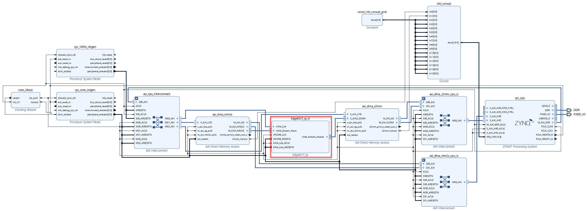
1. Click 4.1 Create Project, then click Run This Task. This task inserts the generated IP core into the Default system with AXI4-Stream interface reference design. As shown in the IP core report, data flows from the ARM processing system through the DMA controller and the AXI4-Stream interface to the HDL Coder generated edge detection IP core. The processing system receives the processed output from the edge detection IP core.
2. Optionally, click the link in the Result pane to open the generated Vivado project. In the Vivado tool, click Open Block Design to view the Zynq design diagram.
Generate Interface Between Host Computer and IP Core
1. In the Generate Software Interface, select Generate host interface script and click Run this Task. The HDL Coder Workflow advisor generates two MATLAB files in your current folder that you can use to prototype your generated IP core directly from MATLAB:
gs_hdlcoder_tunable_edge_detection_setup.m: This function configures thefpgahardware object with the same ports and interfaces that you mapped in the 1.3 Set Target Interface task.gs_hdlcoder_tunable_edge_detection_interface.m: This file creates a connection to your FPGA hardware for reading and writing data.
2. In the HDL Workflow Advisor, run the rest of the tasks to build and download the FPGA bitstream.
Live Frame-Based Model Running on FPGA
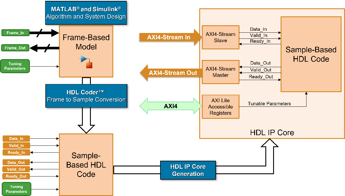
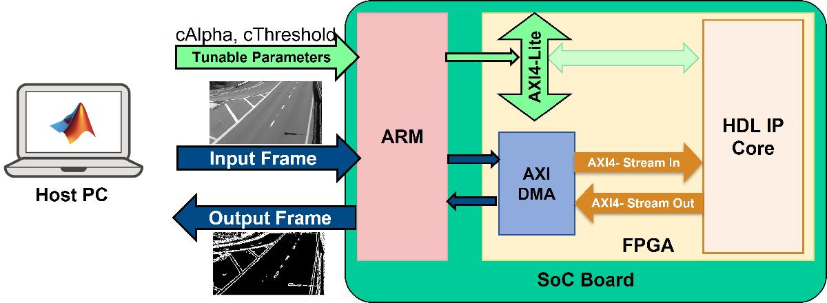
You can interact with the FPGA design by reading and writing data from MATLAB on the host computer as described in the Interact with FPGA Design from Host Computer section of the Prototype Generated IP Core on Hardware using FPGA I/O. The host computer sends and receive frames of data from the System on Chip (SoC) board as shown below in the high level architecture of the system:
This live script uses the generated script file as a starting point to test the frame-based model deployed on the FPGA.
open hdlcoder_frame_edge_detection_script.mlx
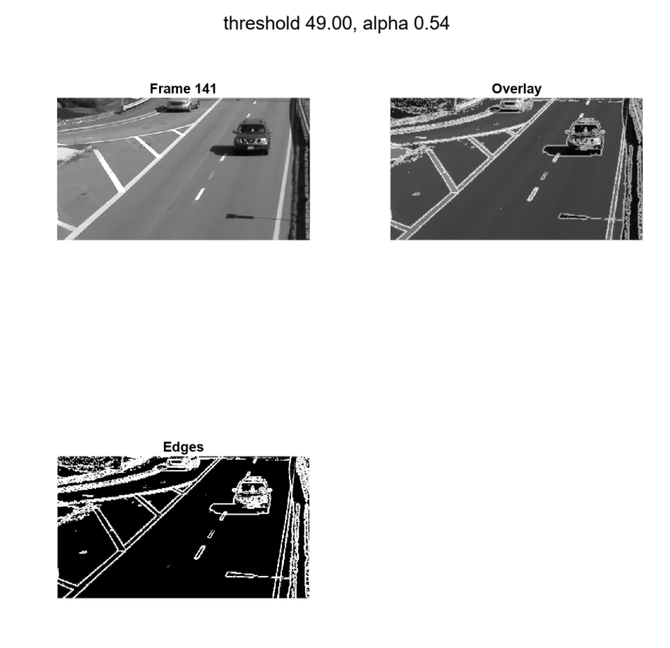
In the Write/Read DUT ports section of the hdlcoder_frame_edge_detection_script script, the code performs edge detection for every 20th frame for the first 200 frames of the visiontraffic.avi video and varies the cAlpha and cThreshold parameters as shown below
vidObj = VideoReader('visiontraffic.avi');
h = figure();
set(h, 'Position', [0 0 800 800])
for ii=1:20:200
    % Modify Parameters
    cThreshold = randi([20,90],1); % Vary cthreshold from 20 to 90
    % Write cThreshold value to "cThreshold" port in the DUT (AXI4-Lite)
    writePort(hFPGA, "cThreshold", cThreshold);
    cAlpha = rand(); % Vary cAlpha from 0 to 1
    % Write cAlpha value to "cAlpha" port in the DUT (AXI4-Lite)
    writePort(hFPGA, "cAlpha", cAlpha);
    % Read the iith frame of vidObj
    vidFrame = read(vidObj,ii);
    vidFrameGr = rgb2gray(vidFrame);
    % Write to inputImage DUT port (AXI4-Stream)
    wrValid = writePort(hFPGA, "imageIn", vidFrameGr);
    if wrValid
        subplot(2,2,1), imagesc(vidFrameGr); axis image; axis off; colormap(gray);
        title(sprintf('Frame %d',ii))
    end
    % Read from inputImage DUT port (AXI4-Stream)
    [outputFrame, rdValid] = readPort(hFPGA,"Overlay_Edges");
    if rdValid
        % Display the data read from the DUT
        subplot(2,2,2), imagesc(uint8(bitsliceget(fi(outputFrame),16,9))); axis image; axis off; colormap(gray);
        title('Overlay')
        subplot(2,2,3), imagesc(uint8(bitsliceget(fi(outputFrame),8,1))); axis image; axis off; colormap(gray);
        title('Edges')
        sgtitle(sprintf('threshold %0.2f, alpha %0.2f',cThreshold, cAlpha))
        drawnow
    else
        continue;
    end
end
When you finish the example, run the last line of the script to release any hardware resources used by the fpga object:
release(hFPGA);