HDL Filter Architectures
The HDL Coder™ software provides architecture options that extend your control over speed vs. area tradeoffs in the realization of filter designs. To achieve the desired tradeoff for generated HDL code, you can either specify a fully parallel architecture, or choose one of several serial architectures. Configure a serial architecture using the SerialPartition and ReuseAccum parameters. You can also choose a frame-based filter for increased throughput.
Use pipelining parameters to improve speed performance of your filter designs. Add pipelines to the adder logic of your filter using AddPipelineRegisters for scalar input filters, and AdderTreePipeline for frame-based filters. Specify pipeline stages before and after each multiplier with MultiplierInputPipeline and MultiplierOutputPipeline. Set the number of pipeline stages before and after the filter using InputPipeline and OutputPipeline. The architecture diagrams show the locations of the various configurable pipeline stages.
Fully Parallel Architecture
This option is the default architecture. A fully parallel architecture uses a dedicated multiplier and adder for each filter tap. The taps execute in parallel. A fully parallel architecture is optimal for speed. However, it requires more multipliers and adders than a serial architecture, and therefore consumes more chip area. The diagrams show the architectures for direct form and for transposed filter structures with fully parallel implementations, and the location of configurable pipeline stages.
Direct Form
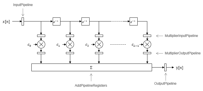
By default, the block implements linear adder
logic. When you enable AddPipelineRegisters,
the adder logic is implemented as a pipelined adder tree. The adder
tree uses full-precision data types. If you generate a validation
model, you must use full precision in the original model to avoid
validation mismatches.
Transposed
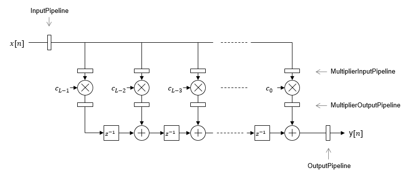
The AddPipelineRegisters
parameter has no effect on a transposed filter
implementation.
Serial Architectures
Serial architectures reuse hardware resources in time, saving chip area. Configure a serial architecture using the SerialPartition and ReuseAccum parameters. The available serial architecture options are fully serial, partly serial, and cascade serial.
Fully Serial
A fully serial architecture conserves area by reusing multiplier and adder resources sequentially. For example, a four-tap filter design uses a single multiplier and adder, executing a multiply-accumulate operation once for each tap. The multiply-accumulate section of the design runs at four times the filter's input/output sample rate. This design saves area at the cost of some speed loss and higher power consumption.
In a fully serial architecture, the system clock runs at a much higher rate than the sample rate of the filter. Thus, for a given filter design, the maximum speed achievable by a fully serial architecture is less than that of a parallel architecture.
Partly Serial
Partly serial architectures cover the full range of speed vs. area tradeoffs that lie between fully parallel and fully serial architectures.
In a partly serial architecture, the filter taps are grouped into a number of serial partitions. The taps within each partition execute serially, but the partitions execute in parallel with respect to one another. The outputs of the partitions are summed at the final output.
When you select a partly serial architecture, you specify the number of partitions and the length (number of taps) of each partition. Suppose you specify a four-tap filter with two partitions, each having two taps. The system clock runs at twice the filter's sample rate.
Cascade Serial
A cascade-serial architecture closely resembles a partly serial architecture. As in a partly serial architecture, the filter taps are grouped into a number of serial partitions that execute in parallel with respect to one another. However, the accumulated output of each partition is cascaded to the accumulator of the previous partition. The output of all partitions is therefore computed at the accumulator of the first partition. This technique is termed accumulator reuse. A final adder is not required, which saves area.
The cascade-serial architecture requires an extra cycle of the system clock to complete the final summation to the output. Therefore, the frequency of the system clock must be increased slightly with respect to the clock used in a noncascade partly serial architecture.
To generate a cascade-serial architecture, specify a partly serial architecture with accumulator reuse enabled. If you do not specify the serial partitions, HDL Coder automatically selects an optimal partitioning.
Latency in Serial Architectures
Serialization of a filter increases the total latency of the design by one clock cycle. The serial architectures use an accumulator (an adder with a register) to add the products sequentially. An additional final register is used to store the summed result of all the serial partitions, requiring an extra clock cycle for the operation. To model this latency, HDL Coder inserts a Delay block into the generated model after the filter block.
Full-Precision for Serial Architectures
When you choose a serial architecture, the code generator uses full precision in the HDL code. HDL Coder therefore forces full precision in the generated model. If you generate a validation model, you must use full precision in the original model to avoid validation mismatches.
Frame-Based Architecture
When you select a frame-based architecture and provide an M-sample input frame, the code generator implements a fully parallel filter architecture. The filter includes M parallel subfilters for each input sample.
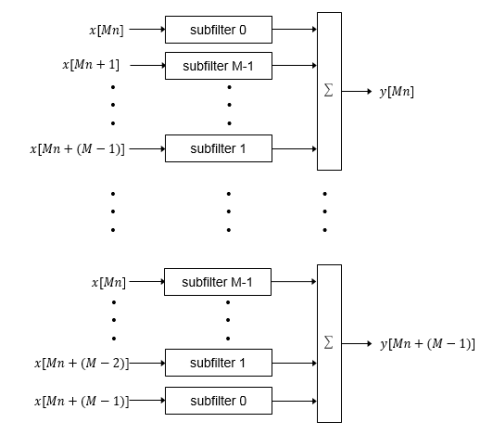
Each of the subfilters includes every Mth coefficient. The subfilter results are added so that each output sample is the sum of each of the coefficients multiplied with one input sample.
| Subfilter | Coefficients |
|---|---|
| 0 | c0,cM, ... |
| 1 | ca,cM+1, ... |
| M–1 | cM–1,c2M–1, ... |
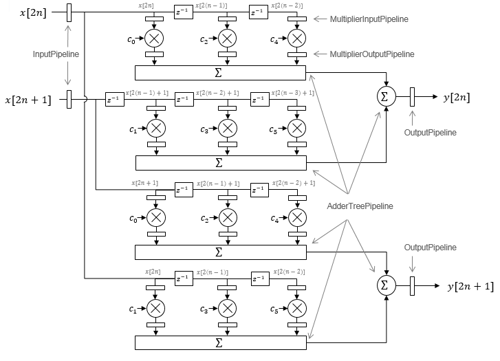
The diagram shows the filter architecture for a frame size of two samples (M = 2), and a filter length of six coefficients. The input is a vector with two values representing samples in time. The input samples, x[2n] and x[2n+1], represent the nth input pair. Every second sample from each stream is fed to two parallel subfilters. The four subfilter results are added together to create two output samples. In this way, each output sample is the sum of each of the coefficients multiplied with one of the input samples.
The sums are implemented as a pipelined adder tree. Set AdderTreePipeline to
specify the number of pipeline stages between levels of the adder tree. To
improve clock speed, it is recommended that you set this parameter to
2. To fit the multipliers into DSP blocks on your
FPGA, add pipeline stages before and after the multipliers using MultiplierInputPipeline and MultiplierOutputPipeline.
For symmetric or antisymmetric coefficients, the filter architecture reuses the coefficient multipliers and adds design delay between the multiplier and summation stages as required.