Set Jumper Switches and Connect Hardware
R2026bIn this step, you set the jumper switches for the hardware board. Depending on the interface you use, you then connect the hardware to the Ethernet, JTAG or PCIe interface.
Set Jumper Switches for Hardware Board
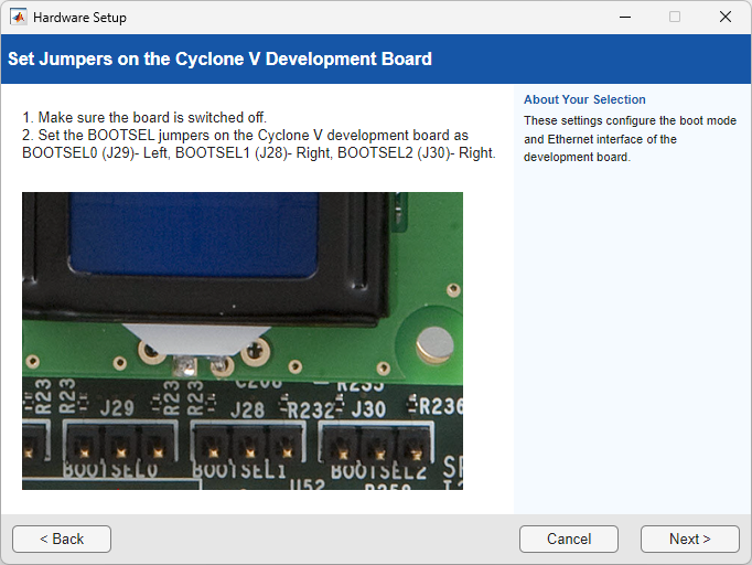
To use the hardware board as a peripheral device, you must configure the jumper switches on the hardware board. The jumper switch settings differ for each board. Turn the board off before setting the jumper switches.
For example, use these switch settings for the Arria® 10 Development Board.
Connect the Hardware Board
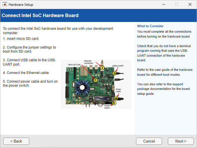
The Connect Intel SoC Hardware Board page describes how to connect the target hardware board to development computer. Wait until the LEDs indicate the readiness of the hardware. Then, wait an additional 20 seconds for the board to boot its operating system and set up communication with the development machine. The LEDs display a green, steady light when the board is ready. If the LEDs do not light up after one minute, press the reset switch and restart the board. When the board is ready, click Next. The software verifies the hardware connection.
Connect Hardware for JTAG or PCIe Interface
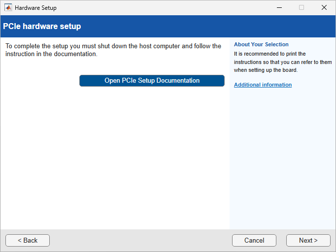
If your board uses the JTAG or PCI Express® interface, you must connect the hardware to the interface. The wizard displays the setup steps for the selected interface on the JTAG Setup or PCIe hardware setup pages.
JTAG Setup Steps
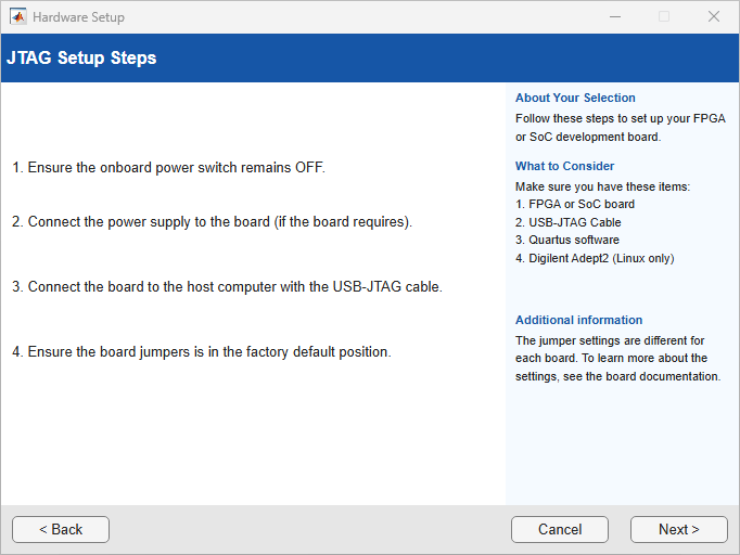
To set up the JTAG interface:
Turn off the board power switch.
Connect the AC power cord to the power plug, and plug the power supply adapter cable into the hardware board.
Use the JTAG download cable to connect the hardware board to the host computer.
Verify that the jumpers on the hardware board are in the factory default position.
Turn the power switch of the hardware board on.
PCI Express Setup Steps
To set up the PCI Express interface on the board:
Turn off the board power switch.
Select the maximum number of PCI Express lanes that the board supports. For details, refer to the user manual for the board.
Supported Board PCI Express Setup Documentation DSP Development Kit, Stratix® V Edition Set the three switches (PCIE_PRSNT2nx1, x4, x8) in dip switch SW6 to ON. This setting selects 8-lane PCIe (default board setting). https://www.altera.com/products/development-kits Cyclone® V GT FPGA Development Kit Set the two switches(PCIe_x1, x4) in dip switch SW3 to ON. This setting selects 4-lane PCIe (default board setting). https://www.altera.com/products/devkit/a1jui0000049utjmam/cyclone-v-gt-fpga-development-kit 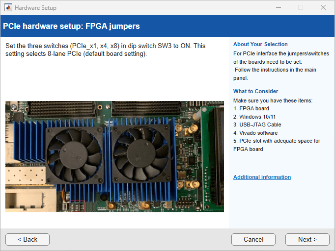
Turn the development computer off.
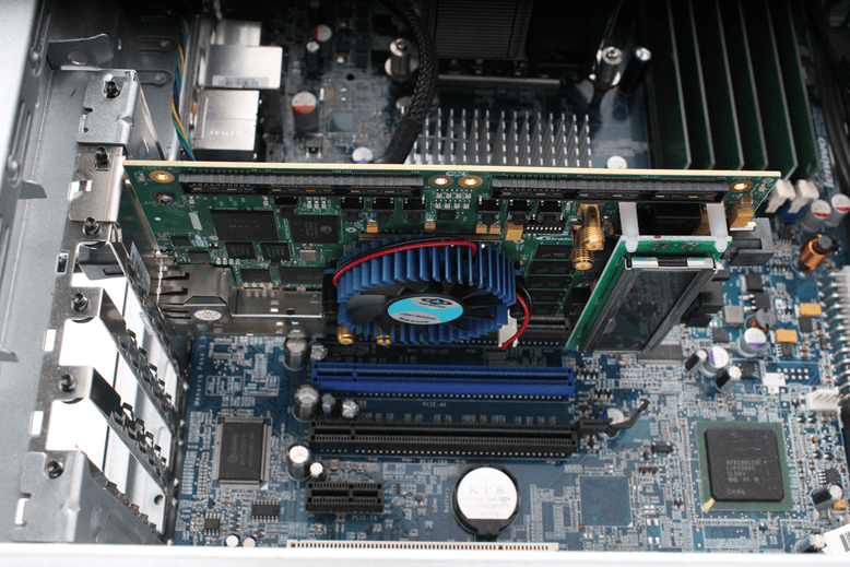
Install the hardware board in a PCI Express slot inside the development computer.
This figure shows a Stratix V board installed in a development computer. This installation procedure applies to supported Altera® VC boards.
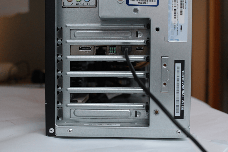
Connect the JTAG cable to the hardware board and the host computer. When you use a PCI Express connection, the JTAG cable is still required to program the FPGA.
Turn the power switch of the hardware board on.
Start up the host computer.
Click, Next.
Connect Intel Agilex 7
If you select the Ethernet interface on an Intel Agilex® 7 SoC board, follow these steps to connect and set up the hardware board.

To configure the SDM, set the S9 switch positions to on-on-on-off and follow these instructions:
Connect the JTAG cable to the board.
Connect the power cable to the board and turn the power on.
To program the SDM by using the JTAG cable, run this command in the MATLAB® Command Window.
programSDM
Turn the board power off and set the S9 switch positions to on-on-off-off.

After you configure the SDM, or if you choose to not configure the SDM, set the S9 switch positions to on-on-off-off and follow these instructions for connecting the hardware:
Remove the SD card from the development computer and insert it into the hardware board.
Connect an Ethernet cable to the board. Connect the other end of the Ethernet cable to the selected NIC.
Connect the power cable.
Turn the power on.
Click, Next.

