Push Button and LED
This example shows you how to use the GPIO blocks in the to control the push-button and the LED components by using the Embedded Coder® Support Package for STMicroelectronics® STM32 Processors
The Embedded Coder® Support Package for STMicroelectronics® STM32 Processors enables you to create and run Simulink models on an STM32F4xx based board. The target includes a library of Simulink blocks for configuring and accessing the STM32F4xx based board sensors, actuators, and communication interfaces.
In this example, you will learn how to use the GPIO blocks in the STM32F4xx processor library.
Prerequisites
It is recommended that you complete these examples:
Required Hardware
To run this example you will need the following hardware:
STMicroelectronics NUCLEO-F429ZI board
USB type A to Mini-B cable
Task 1 - Configure GPIO blocks
In this task, you will configure the GPIO blocks in the STM32F4xx processor library for controlling the LEDs and for reading the state of the user push button on the STMicroelectronics NUCLEO-F429ZI board. There are two user LEDs and a user push button on the STMicroelectronics NUCLEO-F429ZI board. The user push button and the LEDs are connected to GPIO pins. The red user push button is connected to GPIO pin PG14. The LEDs labelled on the board as LD3 and LD4 are connected to GPIO pins PG13 and pin PG14 respectively.
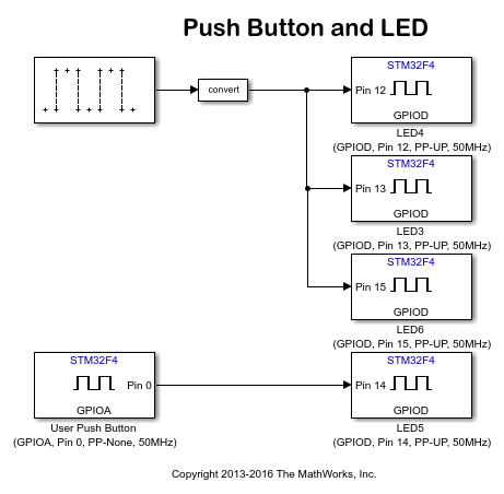
1. Open the stm32f4xx_pb_led model. This model is configured for the STM32F4xx processor target. A pulse generator is used to feed one of the LEDs with a periodic pulse. The period of the pulse is set to 1 second and the duty cycle to 0.5 second. The output of the pulse generator is converted to a logical value to match the GPIO Write block's input port specifications. A GPIO Read block is used to sense the state of the user push button. The output is fed to the red LED (LED5) on the board so that it will glow when the push button is pressed.
open_system('stm32f4xx_pb_led');

2. The settings used in each of the GPIO blocks are annotated below the block in the model. For example, the User Push Button block is configured for GPIO pin PG14. You can view the GPIO port and pin number configuration by double clicking on the block. Additional settings are available in the STM32 CubeMX configuration file IOC indicated by the Configuration Parameters > Hardware Implementation > Target Hardware Resources > Build options > STM32CubeMX project file.

To control the red LED, the GPIO pin PG14 is configured for push pull mode with no pull-up and no pull-down internal resistor enabled. The settings used in each of the GPIO blocks are annotated in this figure for the block in the model. For example, the User Push Button block is configured for GPIOA pin 0. The GPIO A pin 0 is configured for push pull mode with no pull-up and no pull-down internal resistor enabled.

3. Change the Build action to Build, load and run to download and run the generated hex file, stm32f4xx_pb_led.hex, on the STM32F4xx processor board.

4. On the Hardware tab, Click Build, Deploy & Start > Build Stand-Alone to build the model.
5. Observe that the green LED on the board is ON for 0.5 second and OFF for 0.5 second. Press the blue push button to see the red LED glow.
Summary
This example illustrated how to use the GPIO blocks for controlling the LEDs and reading the state of the push button on the STM32F4xx processor board.
close_system('stm32f4xx_pb_led', 0);