QSPI
Libraries:
Embedded Coder Support Package for Infineon AURIX TC4x
Microcontrollers /
AURIX TC4x
Description
Write data to and read data from an SPI peripheral device
The Queued Synchronous Peripheral Interface (QSPI) block accepts 1-D array of data
type int8, uint8, int16,
uint16, int32, and uint32.
The block outputs an array of the same size and data type as the input values.
Examples
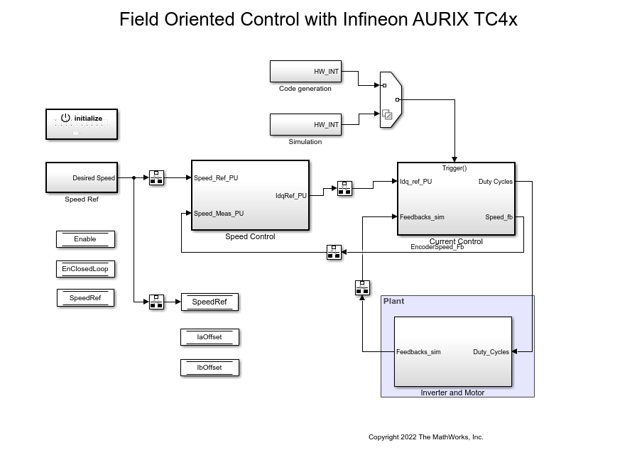
Field-Oriented Control of BLDC with Encoder Using Infineon AURIX Microcontrollers
Implement the field-oriented control (FOC) technique to control the speed of a three-phase brushless DC (BLDC) motor. The FOC algorithm requires rotor position feedback, which is obtained by using an encoder sensor. For more details about FOC, see Field-Oriented Control (FOC) (Motor Control Blockset).
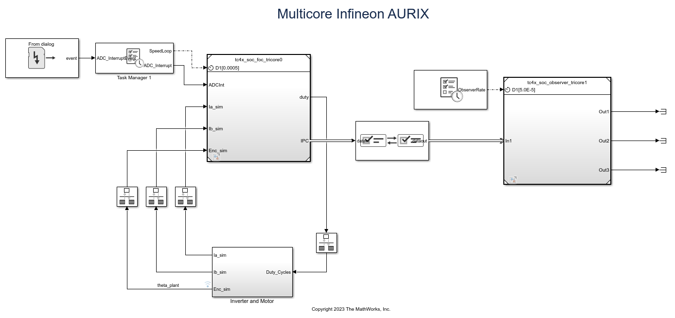
Analyze Sensorless Observers for Field-Oriented Control Using Multiple Cores of Infineon AURIX
Use Embedded Coder® Support Package for Infineon® AURIX™ Microcontrollers for sensorless field-oriented control using multiple cores of an Infineon AURIX microcontroller board. This example uses a top-level model and two referenced models. You use the TriCore0 referenced model to implement a sensor-based field-oriented control (FOC) technique to control the speed of a three-phase brushless DC (BLDC) motor. You use the TriCore1 referenced model to implement and analyze different sensorless algorithms, such as the algorithms implemented in the Flux Observer (Motor Control Blockset), Sliding Mode Observer (Motor Control Blockset), and Extended EMF Observer (Motor Control Blockset) blocks.
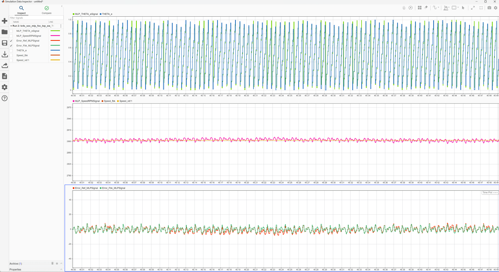
Accelerate AI Based Software Development on Infineon AURIX TC4x Microcontroller
Implement AI based motor control functions using the Model-Based Design approach by deploying a multi-layer perceptron (MLP) neural network on the Infineon® AURIX™ TC4x microcontroller.
Ports
Input
The port inputs the data to be communicated with peripheral device. The datatype is based on the block mask configuration.
Dependencies
To enable this port, set the Transfer mode
parameter to either SPI Transmit and Receive or
SPI Transmit.
Data Types: int8 | uint8 | int16 | uint16 | int32 | uint32
If the Transfer mode is set to either
SPI Transmit and Receive or
SPI Receive, the QSPI block converts the
SoC Blockset™ message SDImsg into output data at
the SDI output port during simulation.
Dependencies
To enable this port, select the Enable simulation port parameter and set the port type as SoC Data (Message based).
If the Transfer mode is set to either
SPI Transmit and Receive or
SPI Receive, this input port acts as
pass-through with the SDI output of QSPI block
during simulation.
Dependencies
To enable this port, select the Enable simulation port parameter and set the port type as Signal.
Output
The port outputs the data received from the peripheral device. The output datatype is based on the block mask configuration.
Dependencies
To enable this port, set the Transfer mode
parameter to either SPI Transmit and Receive or
SPI Receive.
Data Types: int8 | uint8 | int16 | uint16 | int32 | uint32
The block outputs the status of the data that was received, or the
errors that occurred during the data transmission and reception, as a
unit16 scalar value
| Bit | Status |
Bit 0 | Transaction successful |
Bit 1 | Busy |
Bit 2 | Parity Error |
Bit 3 | Configuration Error |
Bit 4 | Baud Rate Error |
Bit 5 | Transmit buffer (Tx FIFO) Overflow Error |
Bit 6 | Tx FIFO Underflow Error |
Bit 7 | Receive buffer (Rx FIFO) Overflow Error |
Bit 8 | Rx FIFO Underflow Error |
Bit 9 | Timeout Error |
For example, the status of 17 (sets 4th and 0th bit) represents successful transaction with baud rate error.
Dependencies
To enable this port, select the Enable status port parameter.
Data Types: uint16
If the Transfer mode is set to either
SPI Transmit and Receive or
SPI Transmit, this port outputs the data
received at SDO port in message form during
simulation.
Dependencies
To enable this port, select the Enable simulation port parameter and set the port type as SoC Data (Message based).
If the Transfer mode is set to either
SPI Transmit and Receive or
SPI Transmit, this port outputs the data
received at SDO port during simulation.
Dependencies
To enable this port, select the Enable simulation port parameter and set the port type as Signal.
Parameters
Basic
Select the QSPI transfer mode.
SPI Transmit and Receive- In this transfer mode, the algorithm waits until the data is received before continuing processing/further processing.When you select this transfer mode, the block configures both output and input ports,
SDOandSDI.SPI Transmit- In this transfer mode, you can transmit the data without waiting to receive. Before initiating the data transfer, ensure the status is1i.e. not in progress from the QSPI Receive block.When you select this transfer mode, the block configures an input port,
SDO.Note
QSPI Receive block is responsible to handle the receive data from the peripheral device. In other words both QSPI Transmit block and QSPI Receive block must be used to complete the data transfer.
SPI Receive- In this transfer mode, you can receive the data from peripheral device.When you select this transfer mode, the block configures an output port,
SDI.Note
The data should be transmitted using QSPI Transmit block before receiving the data. In other words, both QSPI Transmit and QSPI Receive block must be used to complete the data transfer.
Data bits parameter provides the frame length of each data element in the QSPI communication. If the selected data bits is in the range:
2 to 8- the valid data types areint8orunit8.9 to 16- the valid data types areint16orunit16.17 to 32- the valid data types areint32orunit32.
Select this parameter to output status of data transfer.
When you select the Output Status parameter, the block configures an output port, Status.
Specify in seconds how often the block should read the input data.
When you specify this parameter as -1, Simulink® determines the best sample time for the block based on the
block context within the model.
Dependencies
To enable this parameter, set the Transfer
mode to the SPI Receive
Select this parameter to enable peripheral simulation capability.
Select this parameter to configure either the SoC compatible or the Simulink signal based simulation ports to enable peripheral simulation capability.
Dependencies
To view this parameter, select the Enable simulation port parameter.
Advanced
Specify the data length to be received from the peripheral device.
Note
The data length specified must match the data transmitted using QSPI Transmit block.
Dependencies
To enable this parameter, set the Transfer
mode to the SPI Receive
Select the supported data types based on the data bits selected.
Dependencies
To enable this parameter, set the Transfer
mode to either SPI Receive or
SPI Transmit and Receive
Version History
Introduced in R2022b
See Also
MATLAB Command
You clicked a link that corresponds to this MATLAB command:
Run the command by entering it in the MATLAB Command Window. Web browsers do not support MATLAB commands.
웹사이트 선택
번역된 콘텐츠를 보고 지역별 이벤트와 혜택을 살펴보려면 웹사이트를 선택하십시오. 현재 계신 지역에 따라 다음 웹사이트를 권장합니다:
또한 다음 목록에서 웹사이트를 선택하실 수도 있습니다.
사이트 성능 최적화 방법
최고의 사이트 성능을 위해 중국 사이트(중국어 또는 영어)를 선택하십시오. 현재 계신 지역에서는 다른 국가의 MathWorks 사이트 방문이 최적화되지 않았습니다.
미주
- América Latina (Español)
- Canada (English)
- United States (English)
유럽
- Belgium (English)
- Denmark (English)
- Deutschland (Deutsch)
- España (Español)
- Finland (English)
- France (Français)
- Ireland (English)
- Italia (Italiano)
- Luxembourg (English)
- Netherlands (English)
- Norway (English)
- Österreich (Deutsch)
- Portugal (English)
- Sweden (English)
- Switzerland
- United Kingdom (English)


