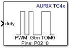
PWM
Libraries:
Embedded Coder Support Package for Infineon AURIX TC4x
Microcontrollers /
AURIX TC4x
Description
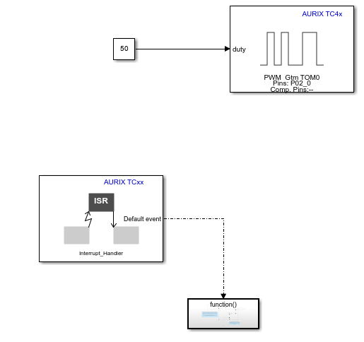
The block input controls the duty cycle of the square waveform for the corresponding
channel. An input value of 0
produces a 0
percent
duty cycle and an input value of 100
produces a
100
percent duty cycle. It accepts N x 1
values of duty cycles corresponding to the N channels
selected.
Examples
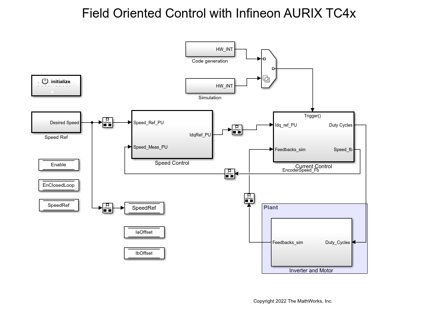
Field-Oriented Control of BLDC with Encoder Using Infineon AURIX Microcontrollers
Implement the field-oriented control (FOC) technique to control the speed of a three-phase brushless DC (BLDC) motor. The FOC algorithm requires rotor position feedback, which is obtained by using an encoder sensor. For more details about FOC, see Field-Oriented Control (FOC) (Motor Control Blockset).
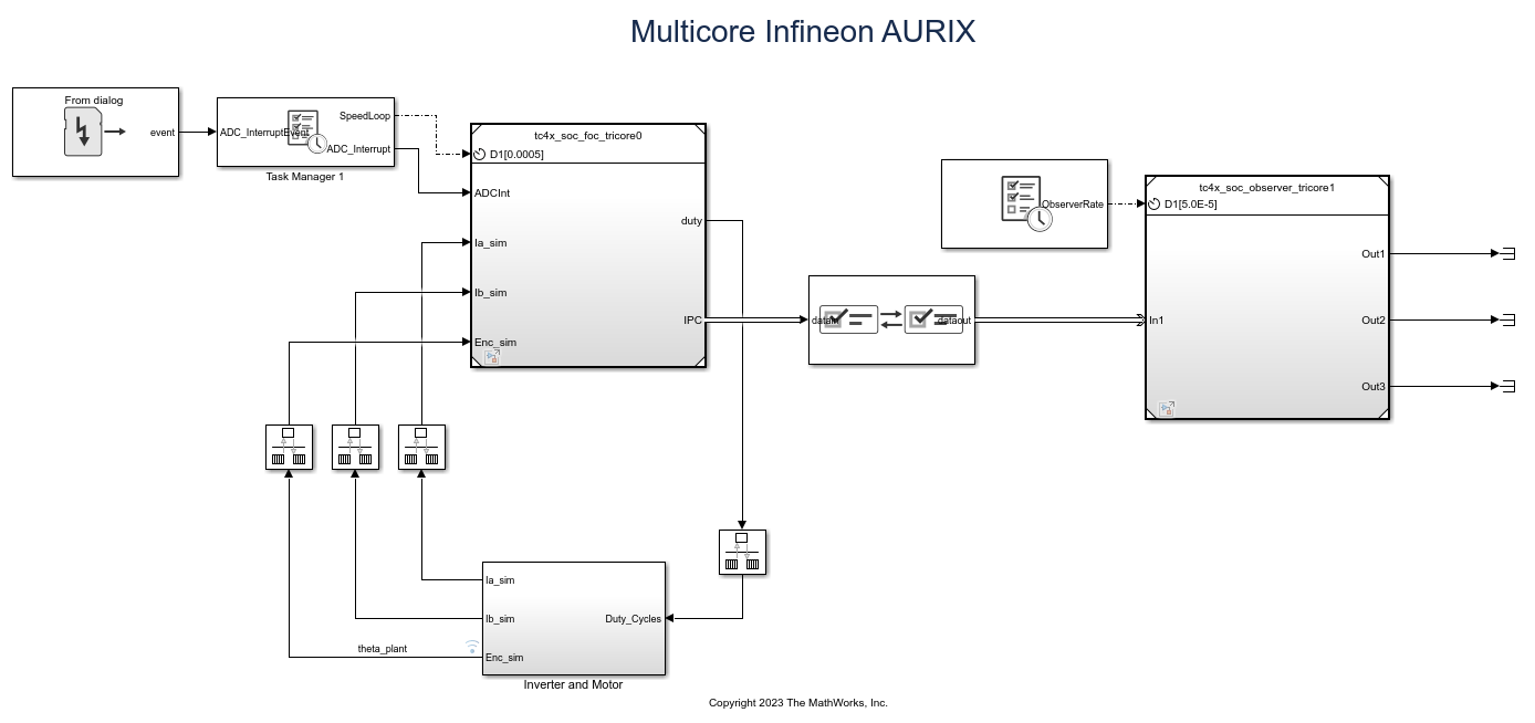
Analyze Sensorless Observers for Field-Oriented Control Using Multiple Cores of Infineon AURIX
Use Embedded Coder® Support Package for Infineon® AURIX™ Microcontrollers for sensorless field-oriented control using multiple cores of an Infineon AURIX microcontroller board. This example uses a top-level model and two referenced models. You use the TriCore0 referenced model to implement a sensor-based field-oriented control (FOC) technique to control the speed of a three-phase brushless DC (BLDC) motor. You use the TriCore1 referenced model to implement and analyze different sensorless algorithms, such as the algorithms implemented in the Flux Observer (Motor Control Blockset), Sliding Mode Observer (Motor Control Blockset), and Extended EMF Observer (Motor Control Blockset) blocks.
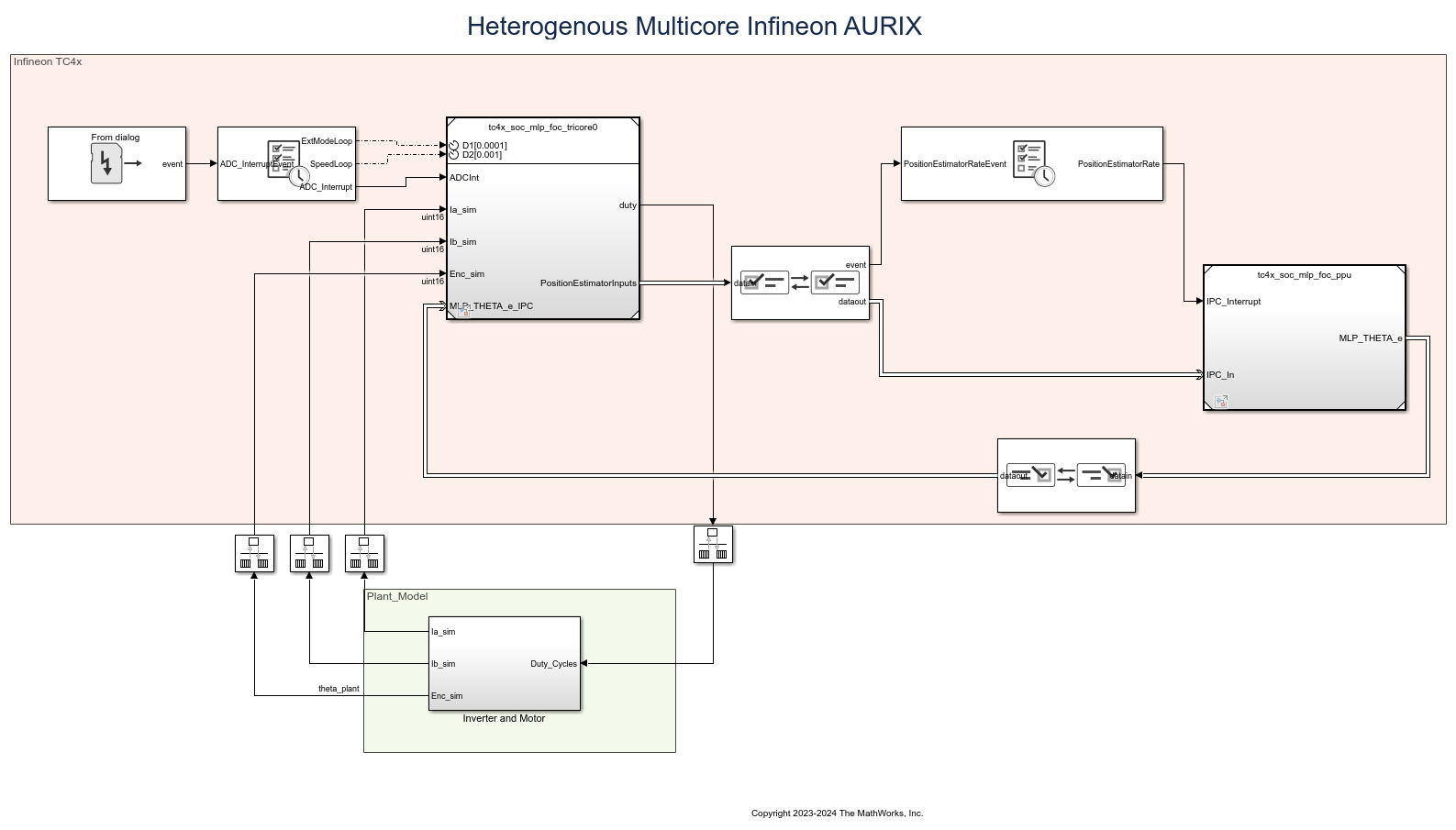
Accelerate AI Based Software Development on Infineon AURIX TC4x Microcontroller
Implement AI based motor control functions using the Model-Based Design approach by deploying a multi-layer perceptron (MLP) neural network on the Infineon® AURIX™ TC4x microcontroller.
Extrapolate Resolver Position Using Timestamp Information
Use the timestamp information in the Resolver block from Embedded Coder® Support Package for Infineon® AURIX™ TC4x Microcontrollers to determine the accurate position of a resolver sensor.
Ports
Input
The value sent to the block input determines the duty cycle of the square wave that the board outputs on the specified PWM pin specified in PWM Peripheral Configuration.
Data Types: Float
The freq port determines the frequency of PWM signal for the selected channels. When you enable the frequency port, the port accepts a scalar input value and sets it as the frequency of the timer unit.
Dependencies
To enable this port, select the Enable frequency input parameter.
The phase port accepts an input value in the range of 0 to
2
pi and sets the phase for the corresponding channel. It
accepts N x 1
values corresponding to the
N channels selected.
Dependencies
To enable this port, select the Enable phase input parameter.
Data Types: single
| double
The dtm_rise port accepts the rising dead time values in seconds. The
timer unit selected in the PWM peripheral app should have DTM sub module
for this feature. It accepts N x 1
values
corresponding to the N channels selected.
Dependencies
To enable this port, select the Enable dead time properties input parameter.
Data Types: Float
| int8
| uint8
| int16
| uint16
| int32
| uint32
The dtm_fall port accepts the falling dead time values in seconds. The
timer unit selected in the PWM peripheral app should have DTM sub module
for this feature. It accepts N x 1
values
corresponding to the N channels selected.
Dependencies
To enable this port, select the Enable dead time properties input parameter.
Data Types: Float
| int8
| uint8
| int16
| uint16
| int32
| uint32
Output
The block outputs the status of the PWM module as one of these values:
255—
Unknown state0—
Initialized1—
Running2—
Stopped3—
Error
Dependencies
To view this port, select the Enable status output parameter.
Data Types: uint8
The port outputs the PWM bus object in the SoC Blockset™ simulation message format during simulation. The PWM bus object contains the information received by the block at the input ports.
Dependencies
To view this port, select the Enable simulation port parameter and set the port type to SoC Data (Message based).
The port outputs the PWM bus object during simulation. The PWM bus object contains the information received by the block at the input ports.
Dependencies
To view this port, select the Enable simulation port parameter and set the port type to Signal.
Parameters
Basic
Select this parameter to set the PWM frequency.
When you select the Enable frequency input
parameter, the block configures an input port,
freq
.
Select this parameter to set the phase of selected channel.
When you select the Enable phase input parameter,
the block configures an input port, phase
.
When you select the Enable status output
parameter, the block configures Status
output
port.
Select this parameter to enable peripheral simulation capability.
Select this parameter to configure either the SoC compatible or the Simulink® signal based simulation ports to enable peripheral simulation capability.
Dependencies
To view this parameter, select the Enable simulation port parameter.
Advanced
Select the required number of PWM channels to send the duty cycles.
The number of channels determines the size of the input ports
phase
, dtm_rise
, and
dtm_fall
.
The number of channels selected depends on the timer module selection in PWM peripheral configuration app.
TOM—
16 channels are availableATOM—
8 channels are available
Select this parameter to determine the PWM dead time value in seconds.
For more information on standard dead time generation, see Dead-Time Module Properties.
Note
Enabling the dead time properties parameter in the block
configures the dtm_rise
and
dtm_fall
input ports. To use the dead
time functionality, go to PWM Peripheral Configuration in the Hardware Mapping
window and configure the corresponding dead time parameters in
Module and Channel
tabs.
Version History
Introduced in R2022b
See Also
MATLAB Command
You clicked a link that corresponds to this MATLAB command:
Run the command by entering it in the MATLAB Command Window. Web browsers do not support MATLAB commands.
웹사이트 선택
번역된 콘텐츠를 보고 지역별 이벤트와 혜택을 살펴보려면 웹사이트를 선택하십시오. 현재 계신 지역에 따라 다음 웹사이트를 권장합니다:
또한 다음 목록에서 웹사이트를 선택하실 수도 있습니다.
사이트 성능 최적화 방법
최고의 사이트 성능을 위해 중국 사이트(중국어 또는 영어)를 선택하십시오. 현재 계신 지역에서는 다른 국가의 MathWorks 사이트 방문이 최적화되지 않았습니다.
미주
- América Latina (Español)
- Canada (English)
- United States (English)
유럽
- Belgium (English)
- Denmark (English)
- Deutschland (Deutsch)
- España (Español)
- Finland (English)
- France (Français)
- Ireland (English)
- Italia (Italiano)
- Luxembourg (English)
- Netherlands (English)
- Norway (English)
- Österreich (Deutsch)
- Portugal (English)
- Sweden (English)
- Switzerland
- United Kingdom (English)