이 페이지는 기계 번역을 사용하여 번역되었습니다. 영어 원문을 보려면 여기를 클릭하십시오.
생성된 C 코드 시뮬레이션 및 검증
튜토리얼의 이 단계에서는 생성된 코드를 실행했을 때 Simulink®에서 모델링한 알고리즘과 수치적으로 동일한지 확인합니다. 테스트 하네스 모델을 사용하여 표준 모드와 SIL 모드에서 ComponentDeploymentFcn를 시뮬레이션한 다음, 시뮬레이션 데이터 인스펙터를 사용하여 시뮬레이션을 비교합니다.
생성 코드를 테스트하기 위해 SIL(Software-in-the-Loop) 및 PIL(Processor-in-the-Loop) 시뮬레이션을 실행할 수 있습니다. SIL 시뮬레이션은 개발 컴퓨터에서 생성 코드를 컴파일하고 실행합니다. PIL 시뮬레이션은 개발 컴퓨터에서 소스 코드를 크로스 컴파일합니다. 그런 다음 PIL 시뮬레이션은 타깃 프로세서나 이와 동등한 명령어 세트 시뮬레이터에서 오브젝트 코드를 다운로드하여 실행합니다. SIL 및 PIL 시뮬레이션을 사용하여 다음을 수행할 수 있습니다.
시뮬레이션과 코드 실행 결과가 수치적으로 동일한지 확인합니다.
코드 커버리지 메트릭과 실행 시간 메트릭을 수집합니다.
IEC 61508, IEC 62304, ISO 26262, EN 50128 또는 DO-178 인증 목표를 달성합니다.
이 튜토리얼에서는 테스트 하네스 ComponentDeploymentFcnHarness를 사용하여 컴포넌트 모델 ComponentDeploymentFcn에 대한 시뮬레이션과 코드 실행 결과가 동일한지 확인하는 방법을 보여줍니다. 하지만 Simulink Test™ 라이선스가 있는 경우 Test Manager를 사용하여 컴포넌트 모델에서 테스트 하네스를 만들 수 있습니다. Create or Import Test Harnesses and Select Properties (Simulink Test) 항목을 참조하십시오.
테스트 하네스 모델 검사 및 구성
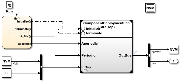
모델 ComponentDeploymentFcnHarness는 Model 블록을 사용하여 테스트 중인 모델 ComponentDeploymentFcn을 참조합니다. 하네스 모델이 참조된 모델에 대한 테스트 입력을 생성합니다. Model 블록을 표준, SIL, PIL 시뮬레이션 모드 간에 쉽게 전환할 수 있습니다.
현재 작업 폴더에
ComponentDeploymentFcn및ComponentDeploymentFcnHarness모델의 사본을 저장합니다.ComponentDeploymentFcnHarness모델을 엽니다.openExample('ComponentDeploymentFcnHarness');
ComponentDeploymentFcn모델을 엽니다.openExample('ComponentDeploymentFcn');ComponentDeploymentFcnHarness모델에서 Model 블록을 마우스 오른쪽 버튼으로 클릭하고 서브시스템 및 모델 참조 > 선택한 Model 블록 새로 고침을 선택합니다.구성 파라미터 대화 상자의 데이터 가져오기/내보내기 창에서 다음 모델 구성 파라미터 설정을 조정하여 두 모델을 모두 시뮬레이션 데이터 인스펙터와 함께 사용하도록 구성합니다.
상태를 선택합니다.
형식를
Dataset으로 설정합니다.기록된 작업 공간 데이터를 시뮬레이션 데이터 인스펙터에 레코딩을 선택합니다.
확인을 클릭합니다. 그런 다음, 모델을 저장합니다.
표준 모드에서 모델 시뮬레이션
표준 모드에서 테스트 하네스 모델을 실행하고 시뮬레이션 데이터 인스펙터에서 결과를 캡처합니다.
모델
ComponentDeploymentFcnHarness에서ComponenDeploymentFcn의 Model 블록을 마우스 오른쪽 버튼으로 클릭합니다. 상황별 메뉴에서 블록 파라미터를 선택합니다.블록 파라미터 대화 상자에서 시뮬레이션 모드 파라미터가
표준으로 설정되어 있는지 확인합니다. 확인을 클릭합니다.ComponentDeploymentFcnHarness를 시뮬레이션합니다.시뮬레이션이 완료되면 시뮬레이션 데이터 인스펙터에서 시뮬레이션 결과를 확인합니다. 시뮬레이션 데이터 인스펙터가 아직 열려 있지 않으면 시뮬레이션 탭에서 데이터 인스펙터를 클릭하십시오.
가장 최근(현재) 실행의 경우, 속성 창에서 실행 필드를 더블 클릭한 다음 실행 이름을
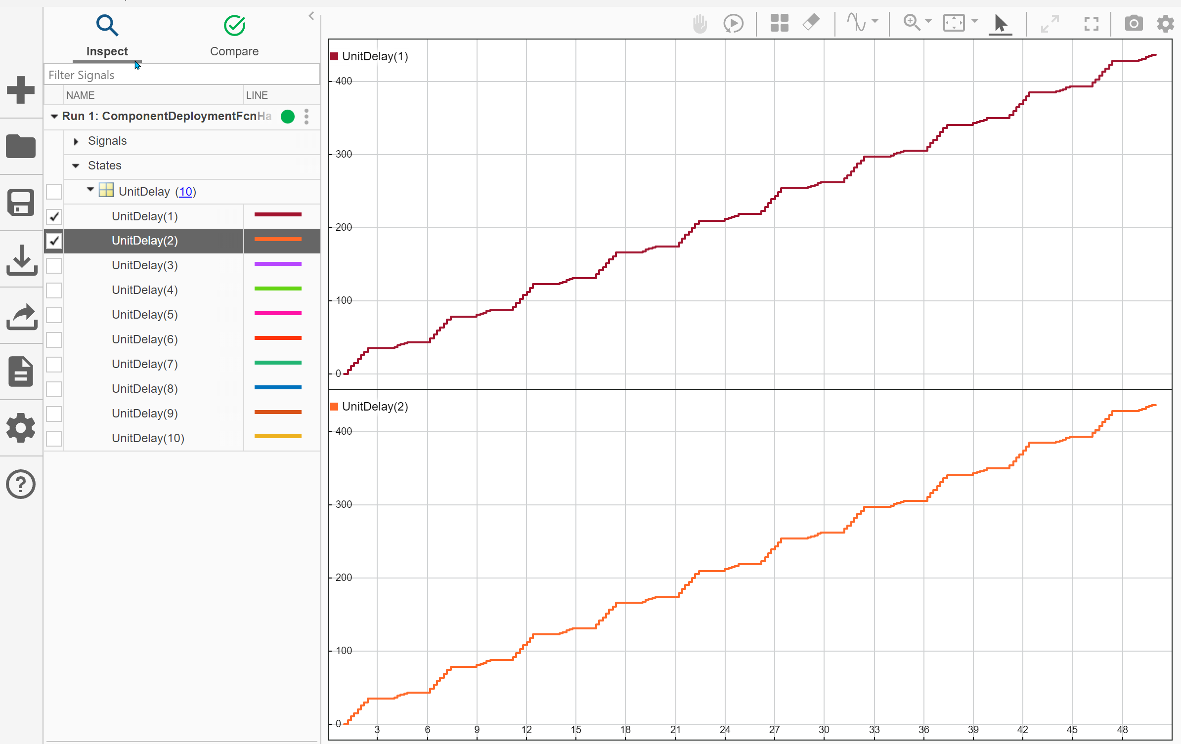
ComponentDeploymentFcn: Normal mode로 변경합니다.시뮬레이션 데이터 인스펙터 시각화를 스파크라인으로 변경합니다. 시각화 아이콘을 클릭한 다음 스파크라인을 클릭하십시오. 그런 다음 신호 필터링 창에서 상태 노드를 확장한 다음 UnitDelay (10)를 선택합니다.
다차원 신호 대화 상자에서 채널로 변환을 선택합니다.
UnitDelay (10) 노드를 확장합니다.
하나 이상의 UnitDelay 신호 선을 선택합니다. 시뮬레이션 데이터 인스펙터는 선택한 채널에 대한 스파크라인을 표시합니다.
이 그림은 UnitDelay (1)와 UnitDelay (2)에 대한 스파크라인을 보여줍니다.

SIL 모드에서 모델 시뮬레이션
SIL 시뮬레이션은 생성된 코드를 개발 컴퓨터에서 컴파일하고 실행합니다. 시뮬레이션 데이터 인스펙터가 결과를 기록합니다.
ComponentDeploymentFcnHarness모델 창에서ComponenDeploymentFcnModel 블록을 마우스 오른쪽 버튼으로 클릭하고 블록 파라미터를 선택합니다.블록 파라미터 대화 상자에서 다음과 같이 파라미터를 변경합니다.
시뮬레이션 모드를
SIL(Software-in-the-Loop)로 설정합니다.코드 인터페이스를
최상위 모델로 설정합니다.
확인을 클릭합니다.
컴포넌트 모델
ComponenDeploymentFcn의 경우 구성 파라미터 대화 상자에서 다음과 같은 모델 구성 파라미터를 변경합니다.코드 생성 창에서 툴체인를
Automatically locate an installed toolchain으로 설정합니다.코드 생성 > 최적화 창에서 내부 데이터 영(0) 초기화 제거를 선택 해제합니다.
구성 변경 사항을 저장합니다.
ComponentDeploymentFcnHarness모델을 시뮬레이션합니다. 진단 뷰어 패널이 열리고 빌드 및 코드 생성 상태가 표시됩니다. 코드 생성 리포트 창이 열리면 나중에 이 튜토리얼을 살펴볼 수 있도록 최소화하십시오.시뮬레이션이 완료되면 시뮬레이션 데이터 인스펙터 속성 창에서 실행 필드를 더블 클릭한 다음 새 실행의 이름을
ComponentDeploymentFcn: SIL mode로 변경합니다.시뮬레이션 데이터 인스펙터 시각화를 스파크라인으로 변경합니다. 시각화 아이콘을 클릭한 다음 스파크라인을 클릭하십시오. 그런 다음 신호 필터링 창에서 상태 노드를 확장한 다음 delay (10)를 선택합니다.
다차원 신호 대화 상자에서 채널로 변환을 선택합니다.
delay (10) 노드를 확장합니다.
하나 이상의 UnitDelay 신호 선을 선택합니다. 시뮬레이션 데이터 인스펙터는 선택한 채널에 대한 스파크라인을 표시합니다.
시뮬레이션 결과 비교
시뮬레이션 데이터 인스펙터에서 다음을 수행할 수 있습니다.
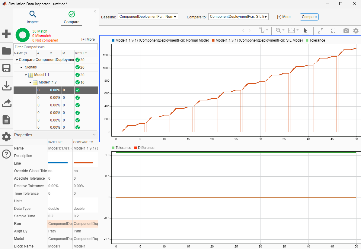
비교 탭을 클릭합니다.
기준 목록에서
ComponentDeploymentFcn: Normal mode를 선택합니다.비교 대상 목록에서
ComponentDeploymentFcn: SIL mode를 선택합니다.비교를 클릭합니다.

이 시뮬레이션 데이터 인스펙터는 표준 모드와 SIL 모드 결과가 일치함을 보여줍니다. 표준 모드 시뮬레이션 결과를 SIL 및 PIL 시뮬레이션과 비교하면 생성된 코드가 예상대로 수행되는지 확인하는 데 도움이 됩니다.
또는 SIL/PIL 관리자 앱을 사용하여 모델에서 생성된 코드를 검증하는 간소화된 워크플로를 사용할 수 있습니다.
다음으로, 생성 코드를 배포할 수 있는 방법을 살펴봅니다.