Filter Noisy Signal Using Fourth-Order Section (FOS) Filter in Simulink
Filter a noisy sinusoidal signal using the Fourth-Order Section Filter block. Obtain the numerator and denominator coefficients of the FOS filter using the Bandpass IIR Filter Design block.
Tune the frequency specifications of the FOS filter during simulation.
Open and Run Model
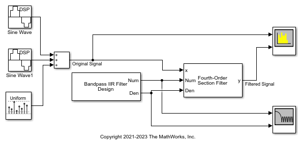
Open the fourthordersectionfilter.slx model.
The input signal in the model is a sum of two sine waves with frequencies of 100 Hz and 350 Hz. The sample rate is 1000 Hz and the number of samples in each frame is 1024. The Random Source block adds zero-mean white Gaussian noise with a variance of 1e-4 to the sum of the sine waves.
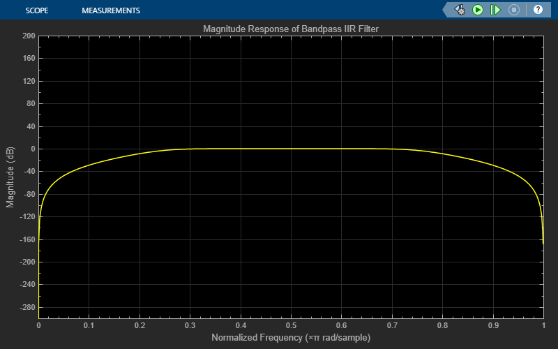
The Bandpass IIR Filter Design block designs a sixth-order bandpass IIR filter with the first and second 3-dB cutoff frequencies of 0.25  rad/sample and 0.75 rad/sample, respectively. The block generates coefficients as a cascade of fourth-order sections. Visualize the frequency response of the filter using the Filter Visualizer.
Run the model.
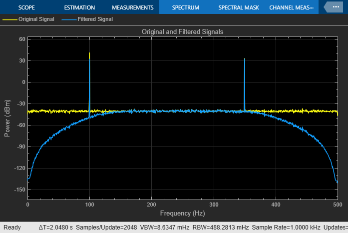
The Fourth-Order Section Filter block filters the noisy sinusoidal signal. Visualize the original sinusoidal signal and the filtered signal using the spectrum analyzer.
Tune Frequency Specification of FOS Filter
During simulation, you can tune the frequency specifications of the FOS filter by tuning the frequency parameters in the Bandpass IIR Filter Design block. The frequency response of the FOS filter updates accordingly.
Change the first 3-dB cutoff frequency to 0.65 rad/sample in the Bandpass IIR Filter Design block. The first tone of the sinusoidal signal is attenuated as it no longer falls in the passband region of the filter.

