Comparison of LDM, CVSD, and ADPCM
This example shows how to compare three different delta-modulation (DM) waveform quantization/coding techniques.
What are DM, LDM, CVSD, and ADPCM?
Delta-modulation (DM) is an Analog-to-Digital coding technique based on differential waveform quantization. At the core of every DM encoder is the error signal
![$$e[n]=u[n]-y[n-1],$$](../../examples/dsp/win64/ComparisonOfLDMCVSDAndADPCMExample_eq08101753912258399093.png)
which is the difference between the input signal to be coded ![$u[n]$](../../examples/dsp/win64/ComparisonOfLDMCVSDAndADPCMExample_eq15125301502800967637.png) and the previous sample of the decoded signal
and the previous sample of the decoded signal ![$y[n-1]$](../../examples/dsp/win64/ComparisonOfLDMCVSDAndADPCMExample_eq13100774872348525997.png) . The sign of the error signal
. The sign of the error signal ![$sign(e[n])$](../../examples/dsp/win64/ComparisonOfLDMCVSDAndADPCMExample_eq09119291288892445125.png) is used to create a differentially quantized data stream. This data stream is a lower-bit-rate signal that can be decoded by a matched decoder on the receiver side in order to achieve data compression, and therefore low data transmission rates.
is used to create a differentially quantized data stream. This data stream is a lower-bit-rate signal that can be decoded by a matched decoder on the receiver side in order to achieve data compression, and therefore low data transmission rates.
In this example, we explore three differential waveform coding techniques: Linear Delta-Modulation (LDM), Continuously Variable Slope Delta-Modulation (CVSD), and Adaptive Differential Pulse Code Modulation (ADPCM). Each method employs two-level (one-bit) encoders, and can be performed at different sampling or data rates. The encoded bit rate is usually directly proportional to the input signal sample rate. For example, in both LDM and CVSD, one bit per sample is used to compute the encoded data stream.
In LDM, a constant step-size is used to approximate the input signal with a single bit per signal sample. In the encoded bit stream, each 1 bit increases the amplitude by the step-size as compared to the previous decoded signal sample. Each 0 bit decreases the amplitude by the step-size. Using LDM, the encoder performance can suffer due to a condition known as "slope overload" when the input signal slope changes too rapidly for the encoder to track it accurately, for instance during high frequency content.
CVSD is LDM with the addition of an adaptive step-size. By adjusting or adapting the step-size to the changes in slope of the input signal, the encoder is able to represent low-frequency signals with greater accuracy without sacrificing as much performance due to slope overload at higher frequencies. When the slope of the input signal changes too quickly for the encoder to keep up with it, the step-size is increased. Conversely, when the input signal slope changes slowly, the step-size is decreased. A slope-overload detector and syllabic filter are used in conjunction with a pulse amplitude modulator (PAM) to accomplish the step-size adaptation. CVSD is used in both commercial and military communications where "toll quality" or "communications quality" is required, yet low computation complexity and low memory requirements are desirable. Two examples of this technique are U.S. MIL-STD-188-113 (16 kbs and 32kbs CVSD) and U.S. Federal Standard 1023 (12 kbs CVSD). In addition, encoded CVSD data can be encrypted and made more secure, which is desirable for many wireless communications applications including speech and general-purpose audio coding.
ADPCM is similar to CVSD, however it provides more accuracy and therefore preserved frequency bandwidth at the expense of additional computational requirements for the adaptation step-size calculations.
Implementing the Encoders and Decoders in Simulink
The attached library dspwvfmcdlib.slx offers Simulink implementations of all three coding methods, LDM, CVSD, and ADPCM.

Comparison of The Encoding Techniques in Simulink
The encoding techniques are compared in the model dspdltmd.slx. All three use the same common analog input.

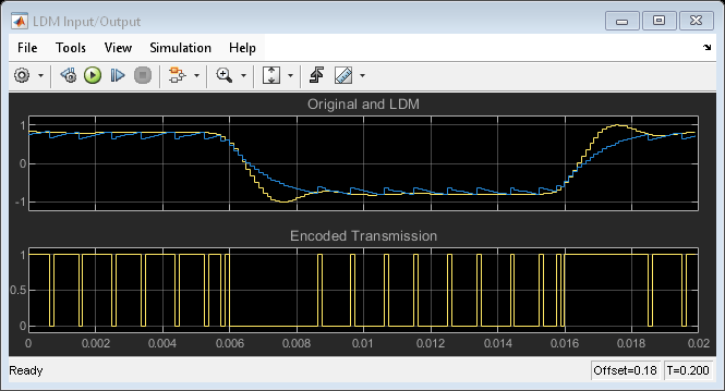
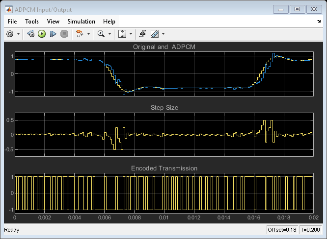
Compare the decoded signal against the input and the encoded signal. The model's scopes show the behavior of the three coding techniques. The first display in each scope shows the original signal in yellow and the recovered signal in magenta that has been encoded and then decoded. You can observe the response of each technique to both constant and rapidly changing signal regions.
Because LCM uses a constant step size, it exhibits slope overload while the signal is changing rapidly and granular noise while the signal is constant. Both CVSD and ADPCM mitigate these problems using a variable step size.
For both CVSD and ADPCM the variable step size is shown in the center display. For all three techniques the one-bit encoded transmission signal is shown in the lower display.


References
[1] Proakis, J. G. Digital Communications. Third Ed. Sec. 3 ("Source Coding"). McGraw Hill. 1995.
[2] Taylor, D. S. "Design of Continuously Variable Slope Delta Modulation Communication Systems." Application Note AN1544/D. Motorola®, Inc. 1996.
[3] "Continuously Variable Slope Delta Modulation: A Tutorial." Application Doc. #20830070.001. MX-COM, Inc., Winston-Salem, North Carolina, 1997.
[4] Conahan, S., Alva, C., and Norris, J. "Implementation of a Real-time 16 kbps CVSD Digital Voice Codec on a Fixed-point DSP." International Conference on Signal Processing Applications and Technology (ICSPAT) Proceedings, Vol. 1. 1998. pp. 282-286.