Differentiator Filter (Obsolete)
Design differentiator filter
Compatibility
Note
The Differentiator Filter (Obsolete) block has been replaced by the Differentiator Filter block. Existing instances of the Differentiator Filter (Obsolete) block will continue to operate. For new models, use the Differentiator Filter block.
Library
Filtering / Filter Designs
dspfdesign
Description
This block brings the filter design capabilities of the filterBuilder function to the Simulink® environment.
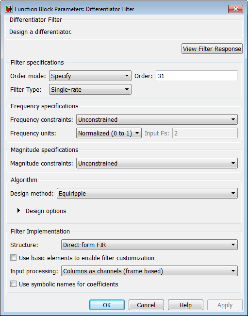
Dialog Box
See Differentiator Filter Design — Main Pane for more information about the parameters of this block. The Data Types and Code Generation panes are not available for blocks in the DSP System Toolbox™ Filter Designs library.
- View filter response
This button opens the Filter Visualization Tool (FVTool) from the Signal Processing Toolbox™ product. You can use the tool to display:
Magnitude response, phase response, and group delay in the frequency domain.
Impulse response and step response in the time domain.
Pole-zero information.
The tool also helps you evaluate filter performance by providing information about filter order, stability, and phase linearity. For more information on FVTool, see the Signal Processing Toolbox documentation.
Filter Specifications
- Order mode
Select either
MinimumorSpecify(the default). SelectingSpecifyenables the Order option so you can enter the filter order.- Order
Enter the filter order. This option is enabled only if you set the Order mode to
Specify. The default order is 31.- Filter type
Select
Single-rate,Decimator,Interpolator, orSample-rate converter. Your choice determines the type of filter as well as the design methods and structures that are available to implement your filter. By default, the block specifies a single-rate filter.Selecting
DecimatororInterpolatoractivates the Decimation Factor or the Interpolation Factor options respectively.Selecting
Sample-rate
                                                converter
activates both factors.
- Decimation Factor
Enter the decimation factor. This option is enabled only if the Filter type is set to
DecimatororSample-rate converter. The default value is 2.- Interpolation Factor
Enter the interpolation factor. This option is enabled only if the Filter type is set to
InterpolatororSample-rate converter. The default value is 2.
Frequency Specifications
The parameters in this group allow you to specify your filter response curve.
- Frequency constraints
This option is only available when you specify the order of the filter design. Supported options are
UnconstrainedandPassband edge and stopband edge.- Frequency units
Use this parameter to specify whether your frequency settings are normalized or in absolute frequency. Select
Normalized
                                (0–1)
to enter frequencies in normalized form. This behavior is the default. To enter frequencies in absolute values, select one of the frequency units from the drop-down list—Hz,kHz,MHz, orGHz. Selecting one of the unit options enables the Input Fs parameter.- Input Fs
Fs, specified in the units you selected for Frequency units, defines the sampling frequency at the filter input. When you provide an input sampling frequency, all frequencies in the specifications are in the selected units as well. This parameter is available when you select one of the frequency options from the Frequency units list.
- Fpass
Enter the frequency at the end of the passband. Specify the value in either normalized frequency units or the absolute units you select in Frequency units.
- Fstop
Enter the frequency at the start of the stopband. Specify the value in either normalized frequency units or the absolute units you select in Frequency units.
Magnitude Specifications
Parameters in this group specify the filter response in the passbands and stopbands. These parameters are only available for minimum-order designs.
- Magnitude constraints
This option is only available when you specify the order of your filter design. The available Magnitude constraints depend on the value of the Frequency constraints parameter. When you set the Frequency constraints parameter to
Unconstrained, the Magnitude constraints parameter must also beUnconstrained. When you set the Frequency constraints parameter toPassband edge and stopband edge, the Magnitude constraints parameter can beUnconstrained,Passband ripple, orStopband attenuation.- Magnitude units
Specify the units for any parameter you provide in magnitude specifications. From the drop-down list, select one of the following options:
Linear— Specify the magnitude in linear units.dB— Specify the magnitude in decibels (default).Squared— Specify the magnitude in squared units.
- Apass
Enter the filter ripple allowed in the passband in the units you choose for Magnitude units, either linear or decibels.
- Astop2
Enter the filter attenuation in the second stopband in the units you choose for Magnitude units, either linear or decibels.
Algorithm
The parameters in this group allow you to specify the design method and structure of your filter.
- Design Method
Lists the design methods available for the frequency and magnitude specifications you entered. When you change the specifications for a filter, such as changing the impulse response, the methods available to design filters changes as well.
- Design Options
The options for each design are specific for each design method. This section does not present all of the available options for all designs and design methods. There are many more that you encounter as you select different design methods and filter specifications. The following options represent some of the most common ones available.
- Density factor
Density factor controls the density of the frequency grid over which the design method optimization evaluates your filter response function. The number of equally spaced points in the grid is the value you enter for Density factor times (filter order + 1).
Increasing the value creates a filter that more closely approximates an ideal equiripple filter but increases the time required to design the filter. The default value of 20 represents a reasonable trade between the accurate approximation to the ideal filter and the time to design the filter.
- Wpass
Passband weight. This option is only available for a specified-order design when Frequency constraints is equal to
Passband edge and stopband
                                                edge
and the Design method isEquiripple.- Wstop
Stopband weight. This option is only available for a specified-order design when Frequency constraints is equal to
Passband edge and stopband
                                                edge
and the Design method isEquiripple.
Filter Implementation
- Structure
For the filter specifications and design method you select, this parameter lists the filter structures available to implement your filter. By default, FIR filters use direct-form structure.
- Use basic elements to enable filter customization
Select this check box to implement the filter as a subsystem of basic Simulink blocks. Clear the check box to implement the filter as a high-level subsystem. By default, this check box is cleared.
The high-level implementation provides better compatibility across various filter structures, especially filters that would contain algebraic loops when constructed using basic elements. On the other hand, using basic elements enables the following optimization parameters:
Optimize for zero gains — Terminate chains that contain Gain blocks with a gain of zero.
Optimize for unit gains — Remove Gain blocks that scale by a factor of one.
Optimize for delay chains — Substitute delay chains made up of n unit delays with a single delay by n.
Optimize for negative gains — Use subtraction in Sum blocks instead of negative gains in Gain blocks.
- Input processing
Specify how the block should process the input. The available options may vary depending on he settings of the Filter Structure and Use basic elements for filter customization parameters. You can set this parameter to one of the following options:
Columns as channels (frame based)— When you select this option, the block treats each column of the input as a separate channel.Elements as channels (sample based)— When you select this option, the block treats each element of the input as a separate channel.
- Rate options
When the Filter type parameter specifies a multirate filter, select the rate processing rule for the block from following options:
Enforce single-rate processing— When you select this option, the block maintains the sample rate of the input.Allow multirate processing— When you select this option, the block adjusts the rate at the output to accommodate an increased or reduced number of samples. To select this option, you must set the Input processing parameter toElements as channels (sample based).
- Use symbolic names for coefficients
Select this check box to enable the specification of coefficients using MATLAB® variables. The available coefficient names differ depending on the filter structure. Using symbolic names allows tuning of filter coefficients in generated code. By default, this check box is cleared.
Supported Data Types
| Port | Supported Data Types |
|---|---|
Input |
|
Output |
|
Version History
Introduced in R2006b