designBandpassIIR
Syntax
Description
[
designs a bandpass IIR filter with the filter order of 10, lower 3-dB cutoff frequency
of 0.25, and higher 3-dB cutoff frequency of 0.75. When you use this syntax, the
function designs the IIR filter using the B
,A
] = designBandpassIIR"default"
window design
method and does not compute the scale values.
B
and A
are the fourth-order section matrices
of the size P-by-5, where P is the number of
filter sections.
The System object™ argument is false
by default. To implement the filter,
assign the filter coefficients to a dsp.FourthOrderSectionFilter
object.
[
specifies options using one or more name-value arguments.B
,A
] = designBandpassIIR(Name=Value
)
For example, [
designs a bandpass IIR filter with the filter order of 30, lower 3-dB cutoff frequency
of 0.3, and higher 3-dB cutoff frequency of 0.8 by using the Chebyshev Type I window
design method.B
,A
] =
designBandpassIIR
(FilterOrder
=30,HalfPowerFrequency1
=0.3,HalfPowerFrequency2
=0.8,DesignMethod
="cheby1",CascadeSectionsForm
="sos")
B
and A
are the second-order section
matrices of the size P-by-3, where P is the number
of filter sections.
When you specify only a partial list of filter parameters, the function designs the filter by setting the other design parameters to their default values.
When you specify any of the numeric input arguments in single precision, the function
designs the filter coefficients in single precision. Alternatively, you can use the Datatype
and
like
arguments to control the coefficients data
type. (since R2024b)
The function supports three design methods. Each design method supports a specific
set of design combinations. For more information, see DesignMethod
.
[
also returns scale values when you specify the B
,A
,SV
] = designBandpassIIR(Name=Value
)HasScaleValues
argument. SV
is a vector of 1s when you set the argument to
false
and a vector of scale values when you set it to
true
.
designs a bandpass IIR filter and implements a filtObj
= designBandpassIIR(Name=Value
)dsp.SOSFilter
object or a dsp.FourthOrderSectionFilter
object.
This syntax applies when you set the SystemObject
argument to
true
.
Examples
Design and Implement Bandpass Chebyshev Type I IIR Filter Using Fourth-Order Sections
Create a dsp.FourthOrderSectionFilter
object.
fosFilt = dsp.FourthOrderSectionFilter
fosFilt = FourthOrderSectionFilter with properties: Numerator: [1 0.1000 0.2000 0.3000 0.4000] Denominator: [1 0.1000 0.2000 0.3000 0.4000]
Create a spectrumAnalyzer
object to visualize the spectra of the input and output signals.
spectrumScope = spectrumAnalyzer(SampleRate=96000,PlotAsTwoSidedSpectrum=false,... ChannelNames=["Input Signal","Filtered Signal"]);
Create a dsp.DynamicFilterVisualizer
object to visualize the magnitude response of the varying filter.
filterViz = dsp.DynamicFilterVisualizer(NormalizedFrequency=true);
Stream in random data and filter the signal using the dsp.FourthOrderSectionFilter
object. Use the designBandpassIIR
function to design the filter coefficients. By default, this function returns a P-by-5 matrix of numerator coefficients and a P-by-5 matrix of denominator coefficients. Assign these coefficients to the dsp.FourthOrderSectionFilter
object.
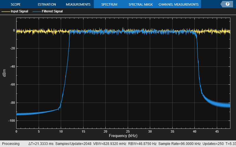
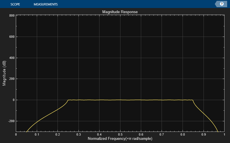
Vary the higher 3-dB cutoff frequency of the filter during simulation. The designBandpassIIR
function recomputes the coefficients based on the updated filter specifications. Redesign the fourth-order section filter using these updated coefficients. Visualize the spectra of the input and filtered signals using the spectrum analyzer.
F3dB2 = 0.6; for idx = 1:500 [b,a] = designBandpassIIR(FilterOrder=30,CascadeSectionsForm="fos",... HalfPowerFrequency1=0.25,... HalfPowerFrequency2=F3dB2,DesignMethod="cheby1"); fosFilt.Numerator = b; fosFilt.Denominator = a; x = randn(1024,1); y = fosFilt(x); spectrumScope(x,y); filterViz(b,a); F3dB2 = F3dB2 + 0.0005; end
Design and Implement Bandpass Butterworth IIR Filter Using Second-Order Sections
Create a dsp.SOSFilter
object, and set the CoefficientSource
property to 'Input port'
so that you can vary the coefficients of the SOS filter through the input port during simulation.
sosFilt = dsp.SOSFilter(CoefficientSource="Input port")
sosFilt = dsp.SOSFilter with properties: Structure: 'Direct form II transposed' CoefficientSource: 'Input port' HasScaleValues: false Use get to show all properties
Create a spectrumAnalyzer
object to visualize the spectra of the input and output signals.
spectrumScope = spectrumAnalyzer(SampleRate=96000,PlotAsTwoSidedSpectrum=false,... ChannelNames=["Input Signal","Filtered Signal"]);
Create a dsp.DynamicFilterVisualizer
object to visualize the magnitude response of the varying filter.
filterViz = dsp.DynamicFilterVisualizer(NormalizedFrequency=true);
Stream in random data and filter the signal using the dsp.SOSFilter
object. Use the designBandpassIIR
function to design the filter coefficients. When you set CascadeSectionsForm
to "sos"
, this function returns a P-by-3 matrix of numerator coefficients and a P-by-3 matrix of denominator coefficients. Assign these coefficients to the dsp.SOSFilter
object.
Vary the lower 3-dB cutoff frequency of the filter during simulation. The designBandpassIIR
function recomputes the coefficients based on the updated filter specifications. Redesign the SOS filter using these updated coefficients. Visualize the spectra of the input and filtered signals using the spectrum analyzer.
F3dB1 = 0.25; for idx = 1:500 [b,a] = designBandpassIIR(FilterOrder=30,CascadeSectionsForm="sos",... HalfPowerFrequency1=F3dB1,... HalfPowerFrequency2=0.75,DesignMethod="butter"); x = randn(1024,1); y = sosFilt(x,b,a); spectrumScope(x,y); filterViz(b,a); F3dB1 = F3dB1 + 0.0005; end
Design and Implement Bandpass Chebyshev Type II IIR Filter Object
Design and implement a bandpass IIR filter object using the designBandpassIIR
function. The function returns a dsp.FourthOrderSectionFilter
object when you set the SystemObject
argument to true
. To design the filter in single-precision, use the Datatype
or like
argument. Alternatively, you can specify any of the numerical arguments in single-precision.
fosFilt = designBandpassIIR(FilterOrder=30,DesignMethod="cheby2",... Datatype="single",SystemObject=true)
fosFilt = FourthOrderSectionFilter with properties: Numerator: [8x5 single] Denominator: [8x5 single]
Create a dsp.DynamicFilterVisualizer
object to visualize the magnitude response of the filter.
filterViz = dsp.DynamicFilterVisualizer(NormalizedFrequency=true,YLimits=[-80 20]); filterViz(fosFilt)
Create a spectrumAnalyzer
object to visualize the spectra of the input and output signals.
spectrumScope = spectrumAnalyzer(SampleRate=44100,PlotAsTwoSidedSpectrum=false,... ChannelNames=["Input Signal","Filtered Signal"]);
Stream in random data and filter the signal using the dsp.FourthOrderSectionFilter
object. Visualize the spectra of the input and filtered signals using the spectrum analyzer.
for idx = 1:500 x = randn(1024,1); y = fosFilt(x); spectrumScope(x,y); end
Input Arguments
Name-Value Arguments
Specify optional pairs of arguments as
Name1=Value1,...,NameN=ValueN
, where Name
is
the argument name and Value
is the corresponding value.
Name-value arguments must appear after other arguments, but the order of the
pairs does not matter.
Example:
designBandpassIIR(FilterOrder=30,HalfPowerFrequency1=0.3,HalfPowerFrequency2=0.7,SystemObject=true)
FilterOrder
— Order of bandpass IIR filter
10
(default) | even nonnegative integer
Order of the bandpass IIR filter, N, specified as an even nonnegative integer.
Data Types: single
| double
| int8
| int16
| int32
| int64
| uint8
| uint16
| uint32
| uint64
HalfPowerFrequency1
— Lower 3-dB cutoff frequency of bandpass IIR filter
0.25
(default) | scalar in the range (0
,1
]
Lower 3-dB cutoff frequency of the bandpass IIR filter,
F3dB1, specified as a normalized scalar in the range
(0
,1
].
The value of HalfPowerFrequency1
must be less than the
value of HalfPowerFrequency2
.
Data Types: single
| double
HalfPowerFrequency2
— Higher 3-dB cutoff frequency of bandpass IIR filter
0.75
(default) | scalar in the range (0
,1
]
Higher 3-dB cutoff frequency of the bandpass IIR filter,
F3dB2, specified as a normalized scalar in the range
(0
,1
].
The value of HalfPowerFrequency1
must be less than the
value of HalfPowerFrequency2
.
Data Types: single
| double
DesignMethod
— Window design method
"default"
(default) |
"butter"
| "cheby1"
|
"cheby2"
Window design method, specified as one of these options:
"default"
–– The function designs the bandpass IIR filter using one of these methods:Chebyshev Type I method when you specify the
PassBandRipple
(APASS) argumentChebyshev Type II method when you specify the
StopbandAttenuation
(ASTOP) argumentButterworth method when you do not specify the
PassBandRipple
(APASS) and theStopbandAttenuation
(ASTOP) arguments
"butter"
–– The function designs the bandpass IIR filter using the Butterworth design method. You can use this method when you specify one of these design specification combinations:FilterOrder
(N)FilterOrder
(N) andHalfPowerFrequency1
(F3dB1)FilterOrder
(N) andHalfPowerFrequency2
(F3dB2)FilterOrder
(N),HalfPowerFrequency1
(F3dB1), andHalfPowerFrequency2
(F3dB2)
"cheby1"
–– The function designs the bandpass IIR filter using the Chebyshev Type I design method. You can use this method when you specify one of these design specification combinations:FilterOrder
(N),HalfPowerFrequency1
(F3dB1), andPassBandRipple
(APASS)FilterOrder
(N),HalfPowerFrequency2
(F3dB2), andPassBandRipple
(APASS)FilterOrder
(N),HalfPowerFrequency1
(F3dB1),HalfPowerFrequency2
(F3dB2), andPassBandRipple
(APASS)
"cheby2"
–– The function designs the bandpass IIR filter using the Chebyshev Type II design method. You can use this method when you specify one of these design specification combinations:FilterOrder
(N),HalfPowerFrequency1
(F3dB1), andStopbandAttenuation
(ASTOP)FilterOrder
(N),HalfPowerFrequency2
(F3dB2), andStopbandAttenuation
(ASTOP)FilterOrder
(N),HalfPowerFrequency1
(F3dB1),HalfPowerFrequency2
(F3dB2), andStopbandAttenuation
(ASTOP)
Data Types: char
| string
PassbandRipple
— Passband ripple of IIR filter
1
(default) | positive scalar
Passband ripple of the IIR filter, APASS, specified as a positive scalar.
To specify the PassbandRipple
argument, set
DesignMethod
to "default"
or
"cheby1"
.
Data Types: single
| double
| int8
| int16
| int32
| int64
| uint8
| uint16
| uint32
| uint64
StopbandAttenuation
— Stopband attenuation of IIR filter
60
(default) | positive scalar
Stopband attenuation of the IIR filter, ASTOP, specified as a positive scalar.
To specify the StopbandAttenuation
argument, set
DesignMethod
to "default"
or
"cheby2"
.
Data Types: single
| double
| int8
| int16
| int32
| int64
| uint8
| uint16
| uint32
| uint64
CascadeSectionsForm
— Form of filter cascade sections
"fos"
(default) | "sos"
Form of filter cascade sections, specified as one of these:
"fos"
–– The function designs the filter using the fourth-order section form and outputs the filter coefficients as P-by-5 matrices."sos"
–– The function designs the filter using the second-order section form and outputs the filter coefficients as P-by-3 matrices.
Data Types: char
| string
HasScaleValues
— Option to compute scale values
false
(default) | true
Option to compute the scale values, SV
, specified as
true
or false
.
To set the HasScaleValues
argument, set
CascadeSectionsForm
to "sos"
.
Data Types: logical
Datatype
— Data type of filter coefficients by type name
"double"
(default) | "single"
Since R2024b
Data type of the filter coefficients, specified by type name as
"double"
or
"single"
.
You can use the Dataype
or the
like
argument to specify the
data type of the filter coefficients, but you cannot use both
arguments at the same time.
If you specify the data type of the filter coefficients using this argument, the function ignores the data types of the other numeric arguments.
Data Types: char
| string
like
— Data type of filter coefficients by prototype
real floating-point value
Since R2024b
Data type of the filter coefficients, specified as a prototype of a real floating-point value.
You can use the Dataype
or the
like
argument to specify the data type of filter
coefficients, but you cannot use both arguments at the same time.
If you specify the data type of the filter coefficients using this argument, the function ignores the data types of the other numeric arguments.
Example: B =
designBandpassIIR(FilterOrder=N,HalfPowerFrequency1=F3dB1,like=single(N))
Example: N = single(110); B =
designBandpassIIR(FilterOrder=N,HalfPowerFrequency1=F3dB1,like=N)
Data Types: single
| double
SystemObject
— Option to create System object
false
(default) |
true
Option to create System object, specified as one of these:
false
–– The function returns second-order section matrices or fourth-order section matrices.true
–– The function returns adsp.SOSFilter
object or adsp.FourthOrderSectionFilter
object.
Data Types: logical
Verbose
— Option to print function call in MATLAB®
false
(default) | true
Option to print the entire function call in MATLAB, specified as one of these:
false
–– The function does not print the function call.true
–– The function prints the entire function call including the default values of theName=Value
arguments that you did not specify when calling the function.Use this argument to view all the values used by the function to design and implement the filter.
Data Types: logical
Output Arguments
B
— Numerator coefficients in second-order section form or fourth-order section form
P-by-3 matrix |
P-by-5 matrix
Numerator coefficients of the bandpass IIR filter in one of these forms:
Second-order section form ––
B
is a P-by-3 matrix, where P is the number of filter sections and equalsceil
(FilterOrder
/2).Fourth-order section form ––
B
is a P-by-5 matrix and P equalsceil
(FilterOrder
/4).
If you specify single-precision values in any of the input arguments, the function designs single-precision filter coefficients. (since R2024a)
If you specify the data type using the
Datatype
or the like
argument, the
function ignores the data types of the other numeric arguments. (since R2024b)
Data Types: single
| double
A
— Denominator coefficients in second-order section form or fourth-order section form
P-by-3 matrix |
P-by-5 matrix
Denominator coefficients of the bandpass IIR filter in one of these forms:
Second-order section form ––
A
is a P-by-3 matrix, where P is the number of filter sections and equalsceil
(FilterOrder
/2).Fourth-order section form ––
A
is a P-by-5 matrix and P equalsceil
(FilterOrder
/4).
The leading denominator coefficient is always 1.
If you specify single-precision values in any of the input arguments, the function designs single-precision filter coefficients. (since R2024a)
If you specify the data type using the
Datatype
and like
arguments, the
function ignores the data types of the other numeric arguments. (since R2024b)
Data Types: single
| double
SV
— Scale values for each section
(P+1)-by-1 vector
Scale values for each section, returned as a (P+1)-by-1
vector, where P is the number of filter sections and equals
ceil
(FilterOrder
/2).
If you set HasScaleValues
to false
,
SV
is a vector of 1s of size
(P+1)-by-1.
If you specify single-precision values in any of the input arguments, the function outputs the scale values in single precision. (since R2024a)
If you specify the data type using the
Datatype
and like
arguments, the
function ignores the data types of the other numeric arguments. (since R2024b)
Dependencies
To enable this output argument, set CascadeSectionsForm
to "sos"
.
Data Types: single
| double
filtObj
— Bandpass IIR filter object
dsp.FourthOrderSectionFilter
object |
dsp.SOSFilter
object
dsp.FourthOrderSectionFilter
dsp.SOSFilter
Bandpass IIR filter object, returned as a:
dsp.FourthOrderSectionFilter
object if you set theCascadeSectionsForm
argument to"fos"
.dsp.SOSFilter
object if you set theCascadeSectionsForm
argument to"sos"
.
Extended Capabilities
C/C++ Code Generation
Generate C and C++ code using MATLAB® Coder™.
When you set the SystemObject
argument to
false
, the function supports code generation with no
limitations.
When you set the SystemObject
argument to
true
, the inputs to the function must be constants when generating
code.
This function supports strict single precision
in generated code. If any of the input arguments are in single precision, or you use the Datatype
and
like
arguments to specify single-precision (since R2024b), the code
you generate uses strictly single-precision arithmetic. (since R2024a)
Version History
Introduced in R2023bR2024b: Specify data type of filter coefficients explicitly
You can now specify the data type of filter coefficients explicitly using the
Datatype
and like
arguments.
R2024a: Support for strict single precision
When you specify single-precision values in any of the input arguments, the function designs filter coefficients and scale values in single precision both in simulation and in generated code.
See Also
Functions
Objects
Blocks
MATLAB Command
You clicked a link that corresponds to this MATLAB command:
Run the command by entering it in the MATLAB Command Window. Web browsers do not support MATLAB commands.
Select a Web Site
Choose a web site to get translated content where available and see local events and offers. Based on your location, we recommend that you select: .
You can also select a web site from the following list
How to Get Best Site Performance
Select the China site (in Chinese or English) for best site performance. Other MathWorks country sites are not optimized for visits from your location.
Americas
- América Latina (Español)
- Canada (English)
- United States (English)
Europe
- Belgium (English)
- Denmark (English)
- Deutschland (Deutsch)
- España (Español)
- Finland (English)
- France (Français)
- Ireland (English)
- Italia (Italiano)
- Luxembourg (English)
- Netherlands (English)
- Norway (English)
- Österreich (Deutsch)
- Portugal (English)
- Sweden (English)
- Switzerland
- United Kingdom (English)
Asia Pacific
- Australia (English)
- India (English)
- New Zealand (English)
- 中国
- 日本Japanese (日本語)
- 한국Korean (한국어)