RTL-SDR Receiver
Receive data from RTL-SDR device
Add-On Required: This feature requires the Communications Toolbox Support Package for RTL-SDR Radio add-on.
Libraries:
Communications Toolbox Support Package for RTL-SDR Radio
Description
The RTL-SDR Receiver block supports communication between Simulink® and the RTL-SDR device, enabling simulation and development for various software-defined radio (SDR) applications. The RTL-SDR Receiver block is a Simulink source that receives data from an RTL-SDR device and outputs a column vector signal of fixed length.
This diagram shows the conceptual overview of receiving radio signals in Simulink by using the Communications Toolbox™ Support Package for RTL-SDR Radio. Simulink interacts with the RTL-SDR Receiver block to receive signals from the radio.

When the host computer is not connected to the radio, you can still use the block to develop a model that propagates sample-time and data-type information. To propagate this information, you must update your model.
This icon shows all ports enabled, including optional ones.
![]()
Examples
Spectrum Analysis of Signals
Perform spectral analysis of signals using either recorded data or real-time reception with RTL-SDR, ADALM-PLUTO, or USRP™ radios, tuning to specific bands and utilizing a spectrum analyzer for viewing and measurements.
FM Broadcast Receiver in Simulink
Build an FM mono or stereo receiver using recorded data or real-time signals with an RTL-SDR, ADALM-PLUTO, or USRP radio.
Frequency Offset Calibration for Receivers in Simulink
Measure and calibrate the frequency offset between a transmitter and receiver with options for using captured signals or real-time reception using an RTL-SDR radio.
Ports
Input
Center frequency in Hz, specified as a positive scalar.
Data Types: double
Receiver gain in dB, specified as a scalar.
Data Types: double
Output
Received data from an RTL-SDR device, returned as one of these values.
Column vector of complex
int16values — The complex values are the raw 16 bit I and Q samples from the RTL-SDR device.Column vector of complex single-precision values — The complex values are scaled to the range of [–1, 1].
Column vector of complex double-precision values — The complex values are scaled to the range of [–1, 1].
To specify the base type, use the Output data type parameter.
Data Types: int16 | single | double
Complex Number Support: Yes
Number of lost samples, returned as a nonnegative integer. When the
RTL-SDR device reports no lost samples, lost is
0.
If your model runs in real time, lost is
0. You can use this output value as a diagnostic
tool to determine real-time execution of the block. For more information
on real-time operation, see Real-Time Operation.
Dependencies
To enable this port, select the Lost samples output port parameter.
Latency of the received data in frames, returned as a nonnegative
integer. When the received frames of data have no latency,
late is less than or equal to
1.
Even when your model runs in real time, received signals can experience latency. You can use this output value as a diagnostic tool to determine real-time execution of the block. For more information on real-time operation, see Real-Time Operation.
Dependencies
To enable this port, select the Latency output port parameter.
Parameters
Radio Connection
Specify the USB address of the RTL-SDR device with which you want to communicate as a nonnegative integer. To update block parameters in the model that is associated with the device specified by Radio address, use the Info parameter to update.
USB Port Address Assignment
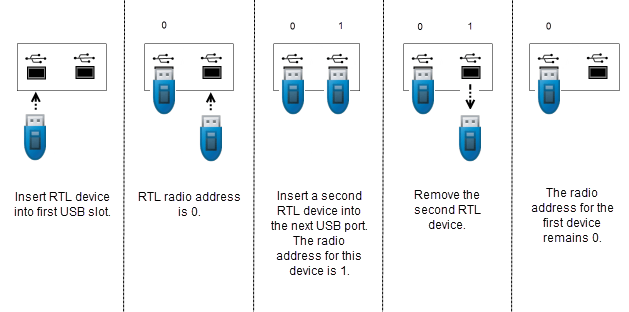
The assignment of USB port addresses can be counterintuitive. If an RTL-SDR device is plugged into the first USB port, it is at address 0. However, if an RTL-SDR device is plugged into any port after the first one, the address varies depending on whether a device is plugged into any of the previous ports. This figure shows how the USB port addresses are assigned when devices are added and then removed in first in, first out (FIFO) order.

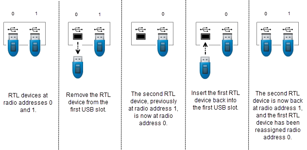
This figure shows how the USB port addresses are assigned when devices are added and then removed from port 0. The radio address for the second RTL-SDR device changes based on whether the first port has an RTL-SDR device in it. To access a radio with the correct radio address, you must keep track of the plugged-in devices in order.

Click this parameter to update block parameters in the model that is
associated with the device specified by the Radio
address parameter. When you click
Info, a dialog box opens that displays information
and parameter settings associated with the device. Use this parameter to
check connectivity between the block and the radio and to synchronize radio
settings between them. If the block is not connected to the radio device,
click Info to return this message in the
RadioName field: 'Cannot find
radio'.
Radio Configuration
Select the source of the center frequency.
Dialog— Set the center frequency by using the Center frequency (Hz) parameter.Input port— Set the center frequency by using the fc input port.
Specify the center frequency in Hz as a positive scalar. The valid range of this parameter depends on the tuner chip of the RTL-SDR device. For a list of tuner chips and their frequency ranges, see [1].
Tunable: No
Dependencies
To enable this parameter, set the Source of center
frequency parameter to
Dialog.
Select the source of the gain.
Dialog— Set the gain by using the Tuner gain (dB) parameter.Input port— Set the gain by using the gain input port.AGC— The RTL-SDR device uses an internal automatic gain control (AGC) algorithm to optimize the receiver gain setting.
Tuner gain in dB, specified as a scalar.
Tunable: No
Dependencies
To enable this parameter, set the Source of gain
parameter to Dialog.
Specify the analog-to-digital converter (ADC) sample rate in Hz, specified as a positive scalar. The valid range of sample rates are [225, 300] kHz and [900, 3200] in kHz. If you set this parameter greater than 2560 kHz, you might observe dropped samples. For more information about the maximum reliable sample rate, see [1].
Tunable: No
Specify the frequency correction in ppm as an integer from –1e4 to 1e4. This parameter corrects the frequency shift in the received data due to local oscillator frequency offset or clock rate inaccuracy.
Tunable: Yes
Data transfer Configuration
Select this parameter to enable the lost output port.
Select this parameter to enable the late output port.
Select the data type of the output signal.
doubleorsingle— The complex values are scaled to the range of [–1, 1].int16— The complex values are the raw 16 bit I and Q samples from the RTL-SDR device.
Tunable: No
Specify the number of samples per frame as a positive integer.
Tunable: No
To produce a set of contiguous frames without an overflow to the radio, select this parameter. Enabling burst mode can help you simulate models that cannot run in real time.
When you select this parameter, specify the desired amount of contiguous data by using the Number of frames in burst and Samples per frame parameters.
Specify the number of frames in a burst as a positive integer.
Tunable: No
Dependencies
To enable this parameter, select the Enable burst mode parameter.
More About
The RTL-SDR Receiver block waits until it receives the number of samples per frame specified by Samples per frame before it returns processing control to the simulation.
References
[1] SDR (Software Defined Radio), https://osmocom.org/projects/rtl-sdr/wiki/Rtl-sdr
Extended Capabilities
C/C++ Code Generation
Generate C and C++ code using Simulink® Coder™.
Version History
Introduced in R2014a
MATLAB Command
You clicked a link that corresponds to this MATLAB command:
Run the command by entering it in the MATLAB Command Window. Web browsers do not support MATLAB commands.
웹사이트 선택
번역된 콘텐츠를 보고 지역별 이벤트와 혜택을 살펴보려면 웹사이트를 선택하십시오. 현재 계신 지역에 따라 다음 웹사이트를 권장합니다:
또한 다음 목록에서 웹사이트를 선택하실 수도 있습니다.
사이트 성능 최적화 방법
최고의 사이트 성능을 위해 중국 사이트(중국어 또는 영어)를 선택하십시오. 현재 계신 지역에서는 다른 국가의 MathWorks 사이트 방문이 최적화되지 않았습니다.
미주
- América Latina (Español)
- Canada (English)
- United States (English)
유럽
- Belgium (English)
- Denmark (English)
- Deutschland (Deutsch)
- España (Español)
- Finland (English)
- France (Français)
- Ireland (English)
- Italia (Italiano)
- Luxembourg (English)
- Netherlands (English)
- Norway (English)
- Österreich (Deutsch)
- Portugal (English)
- Sweden (English)
- Switzerland
- United Kingdom (English)


