주요 콘텐츠

Binary Linear Decoder

Decode linear block code to recover binary vector data

  • Binary Linear Decoder block

Libraries:
Communications Toolbox / Error Detection and Correction / Block

Description

The Binary Linear Decoder block recovers a binary message vector from a binary codeword vector of a linear block code. For more information, see Linear Block Coding.

For proper decoding, the parameter values in this block must match those in the corresponding Binary Linear Encoder block.

Examples

expand all

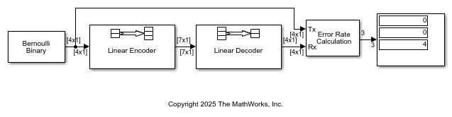
This example shows how to model a simple encoder and decoder using appropriate vector lengths for the code and message.

The cm_binary_linear model includes these blocks:

  • Bernoulli Binary Generator block with Samples per frame set to 4 to match the binary linear encoder message length

  • Binary Linear Encoder block with default parameter values

  • Binary Linear Decoder block with default parameter values

  • Error Rate Calculation block with Output data set to Port

  • Display block connected to the output port of the Error Rate Calculation block

To display the vector length of signals in the model, go to Debug > Diagnostics > Information Overlays > Signals and select Signal Dimensions. The connector lines show the signal attributes. To compile the model, press Ctrl+D. Run the model to display the error rate statistics.

Ports

Input

expand all

Encoded message, specified as a binary column vector containing N elements. N equals the number of columns in the generator matrix specified by the Generator matrix (binary K-by-N matrix) parameter. This port is unnamed on the block mask.

Data Types: single | double | int8 | int16 | int32 | int64 | uint8 | uint16 | uint32 | uint64 | Boolean | fixed point | enumerated | bus
Complex Number Support: Yes

Output

expand all

Decoded message, returned as a column vector output signal containing K elements and having the same data type as the input port, In. K must equal the number of rows in the generator matrix specified by the Generator matrix (binary K-by-N matrix) parameter. This port is unnamed on the block mask.

Parameters

expand all

To edit block parameters interactively, use the Property Inspector. From the Simulink® Toolstrip, on the Simulation tab, in the Prepare gallery, select Property Inspector.

Generator matrix for the code, specified as a K-by-N matrix, where K is the message length and N is the codeword length. For more information, see Linear Block Coding.

Decoding table, specified as 0 or a 2(NK)-by-N matrix that lists correction vectors for each codeword's syndrome.

  • When this parameter is zero (0), the block uses the output of syndtable(H) as the decoding table for the code. The input, H, is an (NK)-by-N parity-check matrix for the code.

  • When this parameter is a matrix, the matrix must be a 2(NK)-by-N binary matrix. For more information, see Decoding Table.

Block Characteristics

Data Types

Boolean | double | fixed point | integer | single

Multidimensional Signals

no

Variable-Size Signals

no

More About

expand all

References

[1] Clark, George C., and J. Bibb Cain. Error-Correction Coding for Digital Communications. Applications of Communications Theory. New York: Plenum Press, 1981.

Extended Capabilities

expand all

C/C++ Code Generation
Generate C and C++ code using Simulink® Coder™.

Version History

Introduced before R2006a