End-to-End Bluetooth BR/EDR PHY Simulation with Multipath Fading Channel, RF Impairments, and Corrections
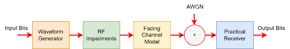
This example shows an end-to-end simulation to measure the bit error rate (BER) and packet error rate (PER) for different Bluetooth® basic rate/enhanced data rate (BR/EDR) physical layer (PHY) packet types by using the Bluetooth® Toolbox. You destort the PHY packet types by adding radio frequency (RF) impairments, multipath fading channel, and the additive white Gaussian noise (AWGN). The practical receiver processes the distorted Bluetooth BR/EDR waveforms to get the BER and PER values. The obtained simulation results show the plots of BER and PER as a function of energy-to-noise density ratio (Eb/No) with different fading channel models.
Bluetooth BR/EDR Radio Specifications
Bluetooth is a short-range Wireless Personal Area Network (WPAN) technology, operating in the globally unlicensed industrial, scientific, and medical (ISM) band in the frequency range of 2.4 GHz to 2.485 GHz. In Bluetooth technology, data is divided into packets. Each packet is transmitted on one of the 79 designated Bluetooth channels. The bandwidth of each channel is 1 MHz. Bluetooth implements the frequency-hopping spread spectrum (FHSS) scheme to switch a carrier between multiple frequency channels by using a pseudorandom sequence known to the transmitter and the receiver.
The Bluetooth standard specifies these PHY modes.
Basic rate (BR) — Mandatory mode, uses Gaussian frequency shift keying (GFSK) modulation with a data rate of 1 Mbps.
Enhanced data rate (EDR) — Optional mode, uses phase shift keying (PSK) modulation with these two variants.
EDR2M — Uses pi/4-DQPSK with a data rate of 2 Mbps
EDR3M — Uses 8-DPSK with a data rate of 3 Mbps
This end-to-end Bluetooth BR/EDR PHY simulation determines the BER and PER performance of multiple Bluetooth packets in the presence of the RF impairments and AWGN. Each packet is generated over a loop of a vector equal to the length of the energy-to-noise density ratio (Eb/No) by using the bluetoothWaveformGenerator function and the bluetoothWaveformConfig object. To accumulate the error rate statistics, RF impairments and AWGN attenuate the generated waveform before passing through the receiver.
RF Impairments and Channel Models
In this example, you distort each Bluetooth BR/EDR packet with these RF impairments.
DC offset
Carrier frequency offset
Static timing offset
Timing drift
Fading channel model
Channel Models
The example supports these channel models.
Rayleigh and Rician Channel Models
Rayleigh and Rician fading channels are useful models of real-world phenomena in wireless communication. These channel models include multipath scattering effects, time dispersion, and Doppler shifts that arise from relative motion between the transmitter and receiver. This figure shows direct and major reflected paths between a stationary radio transmitter and a stationary radio receiver. The shaded shapes represent the reflecting surfaces, such as walls.

The reflected paths non-line of sight (NLOS) result in the arrival of delayed versions of the signal at the receiver. In addition, the radio signal undergoes scattering on a local scale for each major path. Such local scattering typically results from reflections of objects near the receiver. These irresolvable components combine at the receiver and cause a phenomenon known as multipath fading. Due to this phenomenon, each major path behaves as a discrete fading path. Typically, the fading process is characterized by a Rayleigh distribution for an NLOS path and a Rician distribution for a LOS path. For more information about how to use Rayleigh and Rician channel models, see Fading Channels.
Raytracing Channel Model
This channel model uses raytracing in an indoor environment between one transmitter site and one receiver site in a 3-D conference room. The channel model uses computed rays to construct a deterministic channel model specific to the Bluetooth BR/EDR Tx-Rx communication link. You can apply the same raytracing methods to build channel models for indoor and outdoor environments. For more information about how to implement a raytracing channel model in an outdoor environment, see Urban Link and Coverage Analysis Using Ray Tracing.
End-to-End Simulation Procedure
This figure shows the procedure of this end-to-end simulation. After you add the RF impairments, the fading channel model and AWGN distort the Bluetooth BR/EDR waveforms. The practical receiver then receives the noisy waveform.
This figure shows the operational procedure of the practical receiver.

The practical receiver performs these operations on the distorted and noisy waveforms.
Remove the DC offset
Detect the signal bursts
Perform matched filtering
Estimate and correct the timing offset
Estimate and correct the carrier frequency offset
Demodulate the BR/EDR waveform
Perform forward error correction (FEC) decoding
Perform data dewhitening
Perform the header error check (HEC) and cyclic redundancy check (CRC)
Outputs the decoded bits and decoded packet statistics based on the decoded lower address part (LAP), HEC, and CRC
Simulation Configuration
Specify the noise power spectral density (Eb/No) in dB.
EbNo = 2:2:14;
These parameters control the number of packets tested at each Eb/No point.
maxNumErrors— The maximum number of bit errors simulated at each Eb/No point. When the number of bit errors reaches this value, the simulation at this Eb/No point is complete.maxNumPackets— The maximum number of packets simulated at each Eb/No point. When the number of packets reaches this value, the simulation at this Eb/No point is complete.maxNumBits— The maximum number of bits accumulated at each Eb/No point. When the number of bits reaches this value, the simulation at this Eb/No point is complete.
Specify the maxNumErrors, maxNumPackets, and maxNumBits values. For the purpose of this example, specify small values for maxNumErrors and maxNumBits. For statistically meaningful results, you can simulate the example with higher maxNumErrors and maxNumBits values.
maxNumErrors = 100;
maxNumPackets = 1000;
maxNumBits = 1e6;
Bluetooth BR/EDR Waveform
Specify the PHY transmission mode for the Bluetooth BR/EDR waveform.
phyMode =  "BR";
"BR";Based on the specified PHY transmission mode, set the type of Bluetooth BR/EDR packet. These are the Bluetooth BR/EDR packets supported by each PHY transmission mode.
BR—ID,NULL,POLL,FHS,HV1,HV2,HV3,DV,EV3,EV4,EV5,DM1,DM3,DM5,DH1,DH3,DH5, andAUX1.EDR2M—ID,NULL,POLL,FHS,DM1,2-DH1,2-DH3,2-DH5,2-EV3,2-EV5, andAUX1.EDR3M—ID,NULL,POLL,FHS,DM1,3-DH1,3-DH3,3-DH5,3-EV3,3-EV5, andAUX1.
bluetoothPacket =  "DV";
"DV";Specify the samples per symbol. Set this value greater than 1.
sps =  8;
8;Specify the payload length of the input data in bytes.
payloadLength =  18;
18;Create a Bluetooth BR/EDR waveform configuration object by using the bluetoothWaveformConfig object.
txWaveformConfig = bluetoothWaveformConfig(Mode=phyMode, ...
    PacketType=bluetoothPacket, ...
    SamplesPerSymbol=sps, ...
    PayloadLength=payloadLength);
Set the maximum length of "DM1" packets to 17 bytes.
if bluetoothPacket == "DM1"
    txWaveformConfig.PayloadLength = 17;
end
Get the length of the payload by using the getPayloadLength object function.
dataLength = getPayloadLength(txWaveformConfig);
RF Impairments
Set the frequency offset, timing offset, and DC offset parameters to distort the Bluetooth BR/EDR waveform.
freqOffset =6000; % In Hz timingOffset =
0.5; % In samples, less than 1 microsecond timingDrift =
2; % In parts per million dcOffsetPercentage =
2; % Percentage w.r.t maximum amplitude value phaseNoiseLevel = [-130 -136]; % In decibels relative to carrier per hertz phaseFreqOffset = [1e4 1e5]; % In Hz, must be less than sample rate/2
Specify the type of fading channel model as "AWGN", "Rician Channel", "Rayleigh Channel", or "Raytracing Channel".
channelModel =  "Rayleigh Channel";
Simulation Parameters
Preallocate the space to store the BER and PER results.
[ber,per] = deal(zeros(1,length(EbNo)));
If you specify the channel model as "Raytracing Channel", preallocate the space to store data for the site viewer.
if channelModel == "Raytracing Channel"
    visualVar = cell(1,length(EbNo));
end
Specify the number of bits per byte.
bitsPerByte = 8;
Set the code rate value based on the Bluetooth BR/EDR packet type.
if any(bluetoothPacket == ["FHS","DM1","DM3","DM5","HV2","DV","EV4"])
    codeRate = 2/3;
elseif bluetoothPacket == "HV1"
    codeRate = 1/3;
else
    codeRate = 1;
end
For each PHY mode, set the number of bits per symbol.
bitsPerSymbol = 1 + (phyMode == "EDR2M")*1 + (phyMode == "EDR3M")*2;
For each PHY mode, set the signal-to-noise ratio (SNR) values from EbNo values.
snr = EbNo + 10*log10(codeRate) + 10*log10(bitsPerSymbol) - 10*log10(sps);
Specify the sampling frequency of the generated Bluetooth BR/EDR waveform.
sampleRate = sps*1e6;
To configure the RF impairments, create a variable fractional delay object by using the dsp.VariableFractionalDelay (DSP System Toolbox) System object™. Create a phase noise object by using the comm.PhaseNoise System object™.
timingDelay = dsp.VariableFractionalDelay;

phaseNoise = comm.PhaseNoise(Level=phaseNoiseLevel, ...
    FrequencyOffset=phaseFreqOffset, ...
    SampleRate=sampleRate);
Initialize and update the fading channel model.
channelInit = cell(1,1);
if channelModel ~= "AWGN"
    channelInit = helperBluetoothChannelInit(sampleRate,channelModel);
end
Compute the packet length in samples per symbol using bluetoothPacketDuration function.
pktLen = bluetoothPacketDuration(phyMode,bluetoothPacket,payloadLength)*sps;
Simulations
Simulate for each Eb/No point.
for countSnr = 1:length(snr)To ensure that each iteration uses a repeatable set of random numbers, set a random substream index for each iteration.
    stream = RandStream("combRecursive",Seed=100);
    stream.Substream = countSnr;
    RandStream.setGlobalStream(stream);
Create an instance of error rate to check for errors in the received packet.
errorRate = comm.ErrorRate;
Get the configuration parameters of the Bluetooth BR/EDR practical receiver.
rxWaveformConfig = getPhyConfigProperties(txWaveformConfig);
Initialize the parameters for error computation.
    txPacketCount = 0;     % Counter for number of packets at each SNR value
    rxPacketCount = 0;     % Counter for number of detected Bluetooth packets
    bitError = zeros(3,1); % To accumulate bit error for each packet detected
    packetError = 0;       % To accumulate packet error for each packet detected
For each Eb/No point, perform these steps to generate and process the packets.
Generate random bits.
Generate the Bluetooth BR/EDR waveform.
Add the frequency offset, timing offset, and DC offset to the generated Bluetooth BR/EDR waveform.
Pass the RF impaired waveform through the fading channel.
Pass the faded waveform through the AWGN channel.
Pass the noisy waveform through the Bluetooth BR/EDR practical receiver.
Calculate BER and PER.
    while ((bitError(2) < maxNumErrors) && (bitError(3) < maxNumBits) && (txPacketCount < maxNumPackets))
        txBits = randi([0 1],dataLength*bitsPerByte,1);                   % Data bits generation
        txWaveform = bluetoothWaveformGenerator(txBits,txWaveformConfig); % Generate Bluetooth BR/EDR waveform
        txPacketCount = txPacketCount + 1;                                % Increament transmitted packet count by one
Configure and add the RF impairment parameters to the generated Bluetooth BR/EDR waveform.
        % Add frequency offset
        txWaveformCFO = frequencyOffset(txWaveform,sampleRate,freqOffset);

        % Add timing delay
        timingDriftRate = (timingDrift*1e-6)/(length(txWaveform)*sps);   % Timing drift rate
        timingDriftVal = timingDriftRate*(0:1:(length(txWaveform)-1))';  % Timing drift
        delay = (timingOffset*sps) + timingDriftVal;                     % Static timing offset
        txWaveformTimingCFO = timingDelay(txWaveformCFO,delay);

        % Add DC offset
        dcOffset = (dcOffsetPercentage/100)*max(txWaveformTimingCFO);
        txWaveformDCTimingCFO = txWaveformTimingCFO + dcOffset;

        % Add phase noise
        txImpairedWaveform = phaseNoise(txWaveformDCTimingCFO);
Pass the impaired waveform through the fading channel.
        if (channelModel == "AWGN")
            txChanFadedWaveform = txImpairedWaveform;
        else
            % Fading channel filter delay
            chanDelay = info(channelInit.fadingChan).ChannelFilterDelay;

            % Pass through the fading channel model
            txChanFadedWaveform = channelInit.fadingChan([txImpairedWaveform; zeros(chanDelay,1)]);
            txChanFadedWaveform = txChanFadedWaveform(chanDelay+1:end,1);
            if channelModel == "Raytracing Channel"
                visualVar{countSnr} = channelInit.VisualVar;
            end
        end
Add AWGN to the faded waveform.
        sigPower = 10*log10(sum(abs(txChanFadedWaveform(:)).^2)/pktLen);
        rxWaveform = awgn(txChanFadedWaveform,snr(countSnr),sigPower);
Recover data bits from the received noisy waveform by using the helperBluetoothPracticalReceiver helper function.
        [rxBits,decodedInfo,pktStatus] = helperBluetoothPracticalReceiver(rxWaveform,rxWaveformConfig);
        numOfSignals = length(pktStatus);
        rxPacketCount = rxPacketCount + numOfSignals;
Compute the bit error and packet error by comparing the transmitted and received bits.
        checkLength = min(length(txBits),length(rxBits));
        if checkLength
            bitError = errorRate(txBits(1:checkLength),rxBits(1:checkLength));
        end
        packetError = packetError + sum(~pktStatus);
    end
Determine the BER and PER by averaging the pacekt error and bit error over received number of packets.
    per(countSnr) = packetError/rxPacketCount;
    ber(countSnr) = bitError(1);

    % If packet error rate is 1 or NaN, consider average BER of 0.5
    if (((ber(countSnr) == 0) && (per(countSnr) == 1)) || isnan(per(countSnr)))
        ber(countSnr) = 0.5;
        per(countSnr) = 1;
    elseif (((ber(countSnr) > 0 && per(countSnr) == 0)) && (countSnr == 1 || per(countSnr-1) == 1))
        % If CRC fails to detect error in a packet but BER is a positive
        % value, consider error in packet.
        per(countSnr) = 1;
    end
Reset the channel and release the phase noise for different iterations of SNR.
    if channelModel~="AWGN"
        reset(channelInit.fadingChan)
    end
    release(phaseNoise)
Display the message for the specifc SNR value.
    if ~any(bluetoothPacket == ["ID","NULL","POLL"])
        disp(join(["Mode ",phyMode,",", ...
            " simulating for ",channelModel," model,", ...
            " packet type ",bluetoothPacket, ...
            " Eb/No = ",num2str(EbNo(countSnr)),"dB,", ...
            " data length = ",num2str(dataLength),"bytes,", ...
            " BER: ",num2str(ber(countSnr)),",", ...
            " PER: ",num2str(per(countSnr))],""));
    else
        disp(join(["Mode ",phyMode,",", ...
            " simulating for ",channelModel," model,", ...
            " packet type ",bluetoothPacket, ...
            " Eb/No = ",num2str(EbNo(countSnr)),"dB,", ...
            " data length = ",num2str(dataLength),"bytes,", ...
            " BER: ",num2str(ber(countSnr))],""));
    end
end
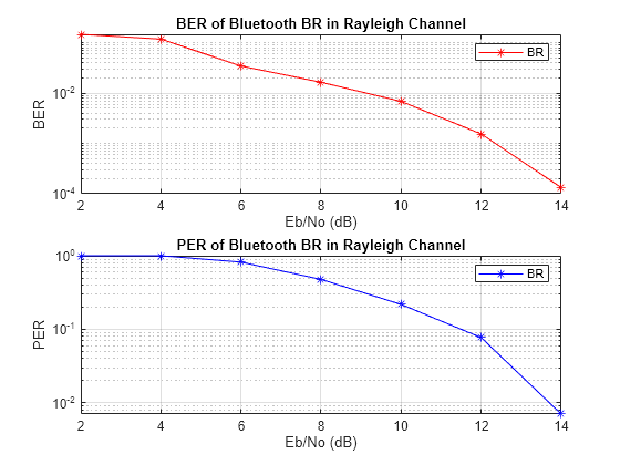
Mode BR, simulating for Rayleigh Channel model, packet type DV Eb/No = 2dB, data length = 18bytes, BER: 0.5, PER: 1
Mode BR, simulating for Rayleigh Channel model, packet type DV Eb/No = 4dB, data length = 18bytes, BER: 0.21181, PER: 1
Mode BR, simulating for Rayleigh Channel model, packet type DV Eb/No = 6dB, data length = 18bytes, BER: 0.079167, PER: 1
Mode BR, simulating for Rayleigh Channel model, packet type DV Eb/No = 8dB, data length = 18bytes, BER: 0.050573, PER: 0.94737
Mode BR, simulating for Rayleigh Channel model, packet type DV Eb/No = 10dB, data length = 18bytes, BER: 0.022398, PER: 0.58824
Mode BR, simulating for Rayleigh Channel model, packet type DV Eb/No = 12dB, data length = 18bytes, BER: 0.011243, PER: 0.42188
Mode BR, simulating for Rayleigh Channel model, packet type DV Eb/No = 14dB, data length = 18bytes, BER: 0.0027827, PER: 0.128
Results and Visualization
For each PHY mode, plot the BER and PER results of each input Eb/No range.
if any(bluetoothPacket == ["ID","NULL","POLL"])
    % Plot only PER
    numOfPlots = 1;
else
    % Plot both BER and PER
    numOfPlots = 2;
    subplot(numOfPlots,1,1),semilogy(EbNo,ber.',"-r*")
    xlabel("Eb/No (dB)")
    ylabel("BER")
    legend(phyMode)
    title(join(["BER of Bluetooth",phyMode,"in",channelModel]))
    hold on
    grid on
end
subplot(numOfPlots,1,numOfPlots),semilogy(EbNo,per.',"-b*")
xlabel("Eb/No (dB)")
ylabel("PER")
legend(phyMode)
title(join(["PER of Bluetooth",phyMode,"in",channelModel]))
hold on
grid on
If you set the fading channel to "Raytracing Channel", configure and display a conference room environment to simulate Bluetooth BR/EDR communication.
if channelModel == "Raytracing Channel"
    visualVar = visualVar{1,end};

    % Show conference room
    viewer = siteviewer(SceneModel=visualVar.MapFileName);

    % Set the icons for transmit site and receiver site
    show(visualVar.TxSite,Icon="bluetoothTxIcon.png");
    show(visualVar.RxSite,Icon="bluetoothRxIcon.png");

    % Plot the rays in the site viewer
    plot(visualVar.Rays,Type="power",ColorLimits=[-30 0]);
end

The raytracing scenario consists of a 3-D indoor conference room, where the blue Bluetooth icon indicates the transmit site and the red Bluetooth icon indicates the receiver site. The rays in the scenario contain LOS components and NLOS components. Each ray reflects a color based on its path loss value. All the rays converge at the receiver site after zero, one, or two interactions (such as reflection and scattering) with a reflecting surface.
Helper Functions
The example uses these helpers.
helperBluetoothChannelInit— Initialize fading channel parametershelperBluetoothPracticalReceiver— Detect, synchronize, and decode the received Bluetooth BR/EDR waveform.
Selected Bibliography
[1] Bluetooth Special Interest Group (SIG), Inc. “Bluetooth® Technology Website – The Official Website for the Bluetooth Wireless Technology. Get up to Date Specifications, News, and Development Info.” Accessed May 24, 2023. https://www.bluetooth.com/.
[2] Bluetooth Special Interest Group (SIG), Inc. “Core Specification – Bluetooth® Technology Website.” Accessed May 24, 2023. https://www.bluetooth.com/specifications/specs/core-specification-5-3/.
[3] International Telecommunication Union Radiocommunication Sector (ITU-R). “M.1225: Guidelines for Evaluation of Radio Transmission Technologies for IMT-2000.” Accessed May 24, 2023. https://www.itu.int/rec/R-REC-M.1225/en.