Dynamic Range Control
Dynamic range control is the adaptive adjustment of the dynamic range of a signal. The dynamic range of a signal is the logarithmic ratio of maximum to minimum signal amplitude specified in dB.
You can use dynamic range control to:
Match an audio signal level to its environment
Protect AD converters from overload
Optimize information
Suppress low-level noise
Types of dynamic range control include:
Dynamic range compressor –– Attenuates the volume of loud sounds that cross a given threshold. They are often used in recording systems to protect hardware and to increase overall loudness.
Dynamic range limiter –– A type of compressor that brickwalls sound above a given threshold.
Dynamic range expander –– Attenuates the volume of quiet sounds below a given threshold. They are often used to make quiet sounds even quieter.
Noise gate –– A type of expander that brickwalls sound below a given threshold.
This tutorial shows how to implement dynamic range control systems using the
compressor, expander, limiter, and noiseGate System objects
from Audio Toolbox™. The tutorial also provides an illustrated example of dynamic
range limiting at various stages of a dynamic range limiting system.
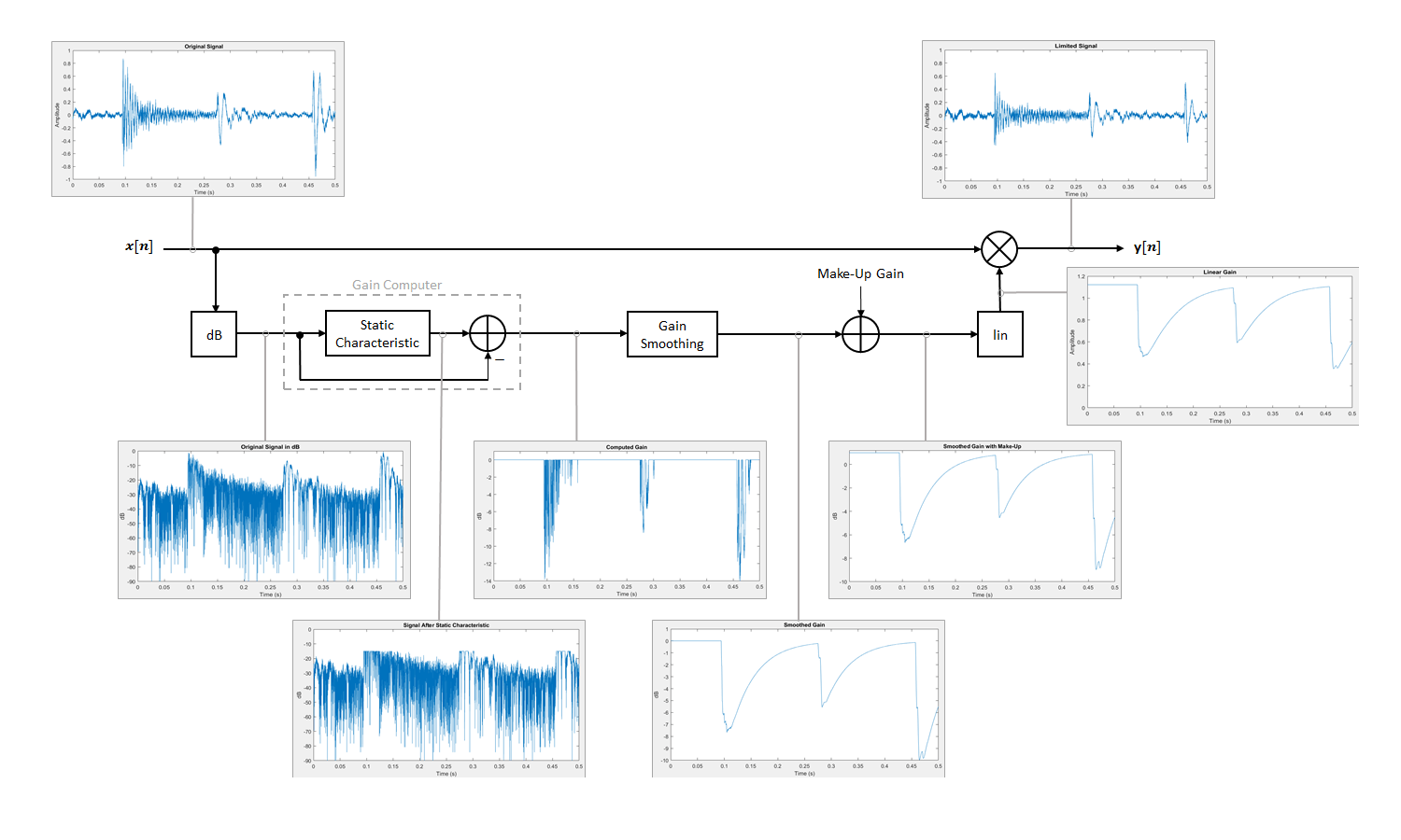
The diagram depicts a general dynamic range control system.

In a dynamic range control system, a gain signal is calculated in a sidechain and then applied to the input audio signal. The sidechain consists of:
Linear to dB conversion:
Gain computation, by passing the dB signal through a static characteristic equation, and then taking the difference:
Gain smoothing over time:
Addition of make-up gain (for compressors and limiters only):
dB to linear conversion:
Application of the calculated gain signal to the original audio signal:
Linear to dB Conversion
The gain signal used in dynamic range control is processed on a dB scale for all dynamic range controllers. There is no reference for the dB output; it is a straight conversion: . You might need to adjust the output of a dynamic range control system to the range of your system.
Gain Computer
The gain computer provides the first rough estimate of a gain signal for dynamic range control. The principal component of the gain computer is the static characteristic. Each type of dynamic range control has a different static characteristic with different tunable properties:
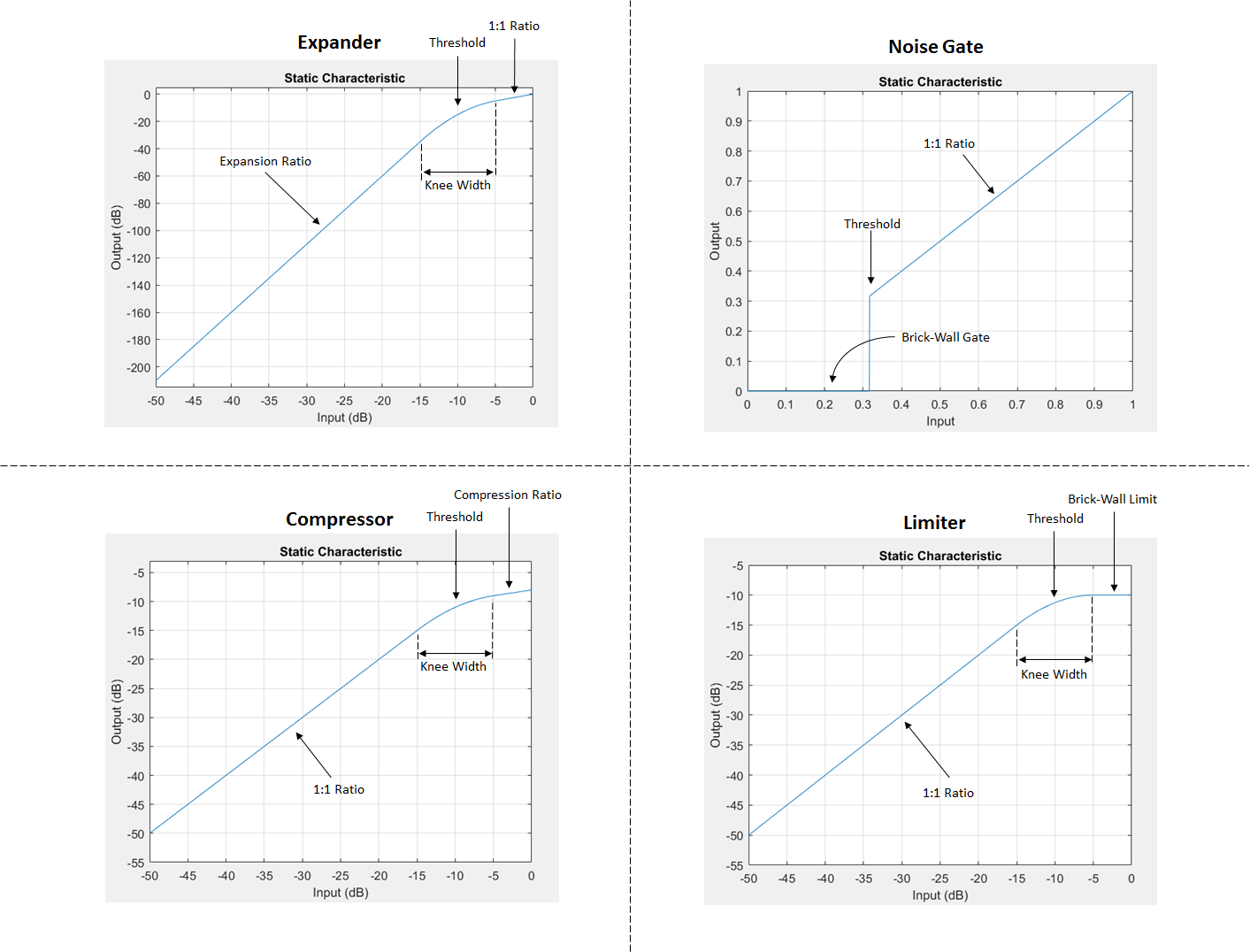
Threshold–– All static characteristics have a threshold. On one side of the threshold, the input is given to the output with no modification. On the other side of the threshold, compression, expansion, brickwall limiting, or brickwall gating is applied.Ratio–– Expanders and compressors enable you to adjust the input-to-output ratio of the static characteristic above or below a given threshold.KneeWidth–– Expanders, compressors, and limiters enable you to adjust the knee width of the static characteristic. The knee of a static characteristic is centered at the threshold. An increase in knee width creates a smoother transition around the threshold. A knee width of zero provides no smoothing and is known as a hard knee. A knee width greater than zero is known as a soft knee.
In these static characteristic plots, the expander, limiter, and compressor each have a 10 dB knee width.

Gain Smoothing
All dynamic range controllers provide gain smoothing over time. Gain smoothing diminishes sharp jumps in the applied gain, which can result in artifacts and an unnatural sound. You can conceptualize gain smoothing as the addition of impedance to your gain signal.
The expander and noiseGate objects have the same
smoothing equation, because a noise gate is a type of expander. The
limiter and compressor objects have the same
smoothing equation, because a limiter is a type of
compressor.
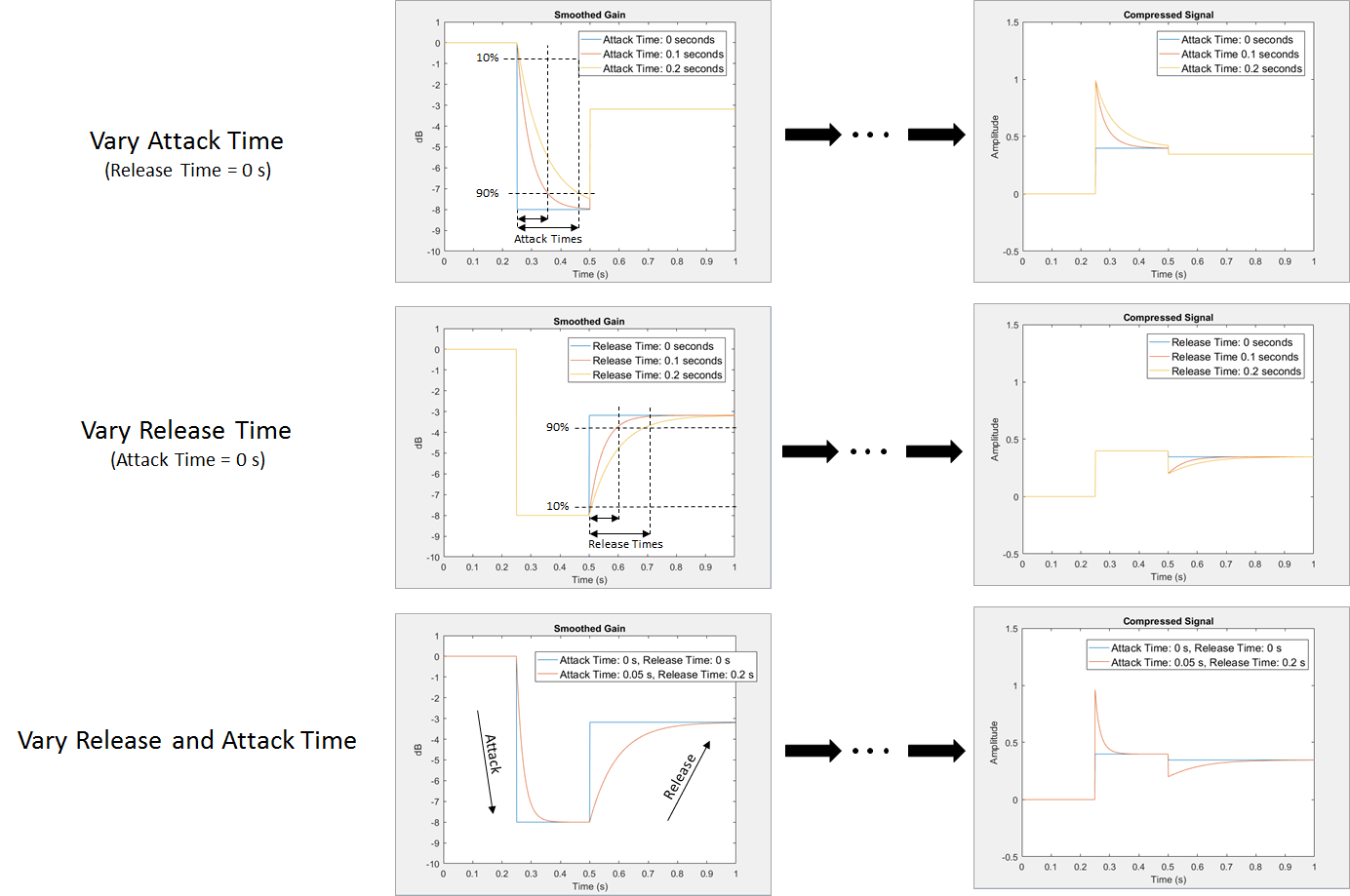
The type of gain smoothing is specified by a combination of attack time, release time, and hold time coefficients. Attack time and release time correspond to the time it takes the gain signal to go from 10% to 90% of its final value. Hold time is a delay period before gain is applied. See the algorithms of individual dynamic range controller pages for more detailed explanations.
Smoothing Equations
expander and
noiseGate
αA and αR are determined by the sample rate and specified attack and release time:
k is the specified hold time in samples.
CA and CR are hold counters for attack and release, respectively.
compressor and
limiter
αA and αR are determined by the sample rate and specified attack and release time:
Gain Smoothing Example
Examine a trivial case of dynamic range compression for a two-step input signal. In this example, the compressor has a threshold of –10 dB, a compression ratio of 5, and a hard knee.

Several variations of gain smoothing are shown. On the top, a smoothed gain curve is shown for different attack time values, with release time set to zero seconds. In the middle, release time is varied and attack time is held constant at zero seconds. On the bottom, both attack and release time are specified by nonzero values.

Make-Up Gain
Make-up gain applies for compressors and limiters, where higher dB
portions of a signal are attenuated or brickwalled. The dB reduction
can significantly reduce total signal power. In these cases, make-up
gain is applied after gain smoothing to increase the signal power.
In Audio Toolbox, you can specify a set amount of make-up gain or
specify the make-up gain mode as 'auto'.
The 'auto' make-up gain ensures that a 0 dB input
results in a 0 dB output. For example, assume a static
characteristic of a compressor with a soft knee:
T is the threshold, W is the knee width, and R is the compression ratio. The calculated auto make-up gain is the negative of the static characteristic equation evaluated at 0 dB:
dB to Linear Conversion
Once the gain signal is determined in dB, it is transferred to the linear domain: .
Apply Calculated Gain
The final step in a dynamic control system is to apply the calculated gain by multiplication in the linear domain.
Example: Dynamic Range Limiter
The audio signal described in this example is a 0.5 second interval of a drum track. The limiter properties are:
Threshold = –15 dB
Knee width = 0 (hard knee)
Attack time = 0.004 seconds
Release time = 0.1 seconds
Make-up gain = 1 dB
To create a limiter
System object™ with these properties, at the MATLAB® command prompt,
enter:
dRL = limiter('Threshold',-15,...
              'KneeWidth',0,...
              'AttackTime',0.004,...
              'ReleaseTime',0.1,...
              'MakeUpGainMode','property',...
              'MakeUpGain',1);
This example provides a visual walkthrough of the various stages of the dynamic range limiter system.

Linear to dB Conversion
The input signal is converted to a dB scale element by element.

Gain Computer
The static characteristic brickwall limits the dB signal at –15 dB. To determine the dB gain that results in this limiting, the gain computer subtracts the original dB signal from the dB signal processed by the static characteristic.

Gain Smoothing
The relatively short attack time specification results in a steep curve when the applied gain is suddenly increased. The relatively long release time results in a gradual diminishing of the applied gain.

Make-Up Gain
Assume a limiter with a 1 dB make-up gain value. The make-up gain is added to the smoothed gain signal.

dB to Linear Conversion
The gain in dB is converted to a linear scale element by element.

Apply Calculated Gain
The original signal is multiplied by the linear gain.

References
[1] Zolzer, Udo. "Dynamic Range Control." Digital Audio Signal Processing. 2nd ed. Chichester, UK: Wiley, 2008.
[2] Giannoulis, Dimitrios, Michael Massberg, and Joshua D. Reiss. "Digital Dynamic Range Compressor Design –– A Tutorial And Analysis." Journal of Audio Engineering Society. Vol. 60, Issue 6, 2012, pp. 399–408.
See Also
Compressor | Expander | Limiter | Noise Gate | compressor | expander | limiter | noiseGate