designParamEQ
Design parametric equalizer
The designParamEQ function has changed. For more information, see Version History.
Description
[ designs a parametric equalizer
with options specified using one or more name-value arguments. You can specify
design options, including gain, center frequency, and bandwidth.B,A] =
designParamEQ(Name=Value)
Examples
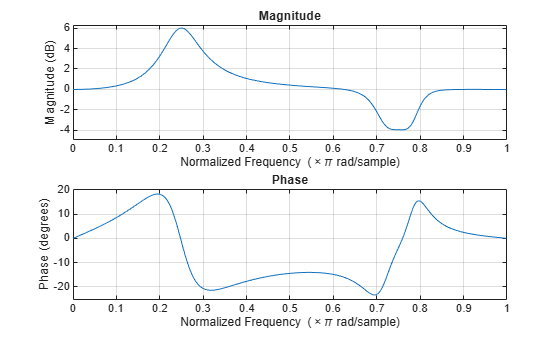
Specify the filter order, peak gain in dB, normalized center frequencies, and normalized bandwidth of the bands of the parametric equalizer.
N = [2, ...
4]; GdB = [
6, ...
-4]; wc = [
0.25, ...
0.75]; bw = [
0.12, ...
0.1];
Generate the filter coefficients using the specified parameters.
[B,A] = designParamEQ(FilterOrder=N,Gain=GdB, ...
CenterFrequency=wc,Bandwidth=bw);Visualize the frequency response of the designed filter.
freqz([B,A]);

Design a second-order sections (SOS) parametric equalizer using designParamEQ and filter an audio stream.
Create audio file reader and audio device writer System objects. Use the sample rate of the reader as the sample rate of the writer.
frameSize = 256;
fileReader = dsp.AudioFileReader("RockGuitar-16-44p1-stereo-72secs.wav",SamplesPerFrame=frameSize);
sampleRate = fileReader.SampleRate;
deviceWriter = audioDeviceWriter(SampleRate=sampleRate);Play the audio signal through your device.
count = 0; while count < 2500 audio = fileReader(); deviceWriter(audio); count = count + 1; end reset(fileReader)
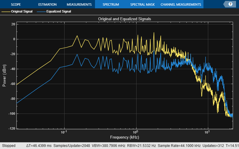
Design an SOS parametric equalizer suitable for use with dsp.SOSFilter.
N = [4,4];
G = [-25,35];
wc = [0.01,0.5];
bw = [0.35,0.5];
[B,A] = designParamEQ(FilterOrder=N,Gain=G, ...
CenterFrequency=wc,Bandwidth=bw);Create an SOS filter.
myFilter = dsp.SOSFilter(B,A);
Create a spectrum analyzer to visualize the original audio signal and the audio signal passed through the parametric equalizer.
scope = spectrumAnalyzer( ... SampleRate=sampleRate, ... PlotAsTwoSidedSpectrum=false, ... FrequencyScale="log", ... Title="Original and Equalized Signals", ... ShowLegend=true, ... ChannelNames=["Original Signal","Equalized Signal"]);
Play the filtered audio signal and visualize the original and filtered spectrums.
count = 0; while count < 2500 originalSignal = fileReader(); equalizedSignal = myFilter(originalSignal); scope([originalSignal(:,1),equalizedSignal(:,1)]); deviceWriter(equalizedSignal); count = count + 1; end
As a best practice, release the objects once done.
release(deviceWriter) release(fileReader) release(scope)

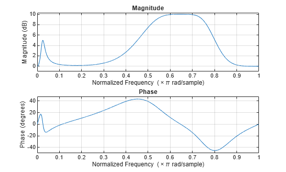
Design a fourth-order sections (FOS) parametric equalizer using designParamEQ and filter an audio stream.
Construct audio file reader and audio device writer System objects. Use the sample rate of the reader as the sample rate of the writer.
frameSize = 256; fileReader = dsp.AudioFileReader( ... "RockGuitar-16-44p1-stereo-72secs.wav",SamplesPerFrame=frameSize); sampleRate = fileReader.SampleRate; deviceWriter = audioDeviceWriter(SampleRate=sampleRate);
Play the audio signal through your device.
count = 0; while count < 2500 x = fileReader(); deviceWriter(x); count = count + 1; end reset(fileReader)
Design FOS parametric equalizer coefficients.
N = [2 4]; G = [5 10]; wc = [0.025 0.65]; Q = [1 1.86]; mode = "fos"; [B,A] = designParamEQ(FilterOrder=N,Gain=G, ... CenterFrequency=wc,QualityFactor=Q,CascadeSectionsForm=mode);
Construct FOS IIR filters.
myFilter = dsp.FourthOrderSectionFilter(B,A);
Visualize the frequency response of the parametric equalizer.
freqz(myFilter)

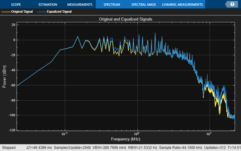
Construct a spectrum analyzer to visualize the original audio signal and the audio signal passed through the parametric equalizer.
scope = spectrumAnalyzer( ... SampleRate=sampleRate, ... PlotAsTwoSidedSpectrum=false, ... FrequencyScale="log", ... Title="Original and Equalized Signals", ... ShowLegend=true, ... ChannelNames=["Original Signal","Equalized Signal"]);
Play the filtered audio signal and visualize the original and filtered spectra.
count = 0; while count < 2500 x = fileReader(); y = myFilter(x); scope([x(:,1),y(:,1)]); deviceWriter(y); count = count + 1; end
As a best practice, release the objects once done.
release(fileReader) release(deviceWriter) release(scope)

Name-Value Arguments
Specify optional pairs of arguments as
Name1=Value1,...,NameN=ValueN, where Name is
the argument name and Value is the corresponding value.
Name-value arguments must appear after other arguments, but the order of the
pairs does not matter.
Example: [B,A] =
designParamEQ(CenterFrequency=0.5,QualityFactor=4) designs a
parametric equalizer with a center frequency of 0.5π rad/sample
and a quality factor of 4.
Normalized center frequency of the equalizer bands, specified as a scalar or row vector.
CenterFrequencymust be real valued and in the range (0,1), where 1 corresponds to the Nyquist frequency (π rad/sample).If you specify
CenterFrequencyas a row vector, thendesignParamEQdesigns one equalizer for each element of the specified row vector.If you specify
CenterFrequencyas a row vector, then you can specify one of these bandwidth specifications:Bandwidth,QualityFactor, orOctaveBandwidth. You cannot specifyBandEdgeFrequenciesin this case. For more information, see Bandwidth Specifications.If you specify
CenterFrequencyand a bandwidth specification (Bandwidth,QualityFactor, orOctaveBandwidth) as row vectors, then both vectors must have the same size.
Data Types: single | double
Normalized bandwidth of the equalizer bands, specified as a scalar or row vector.
Bandwidthmust be real valued and in the range (0,1), where 1 corresponds to the Nyquist frequency (π rad/sample).If you specify
Bandwidth, do not specifyQualityFactor,OctaveBandwidth, orBandEdgeFrequencies. For more information, see Bandwidth Specifications.If you specify
BandwidthandCenterFrequencyas row vectors, then both vectors must be of the same size.
The function measures the normalized bandwidth at G/2 dB, where G is the gain specified
in Gain. If the gain is -Inf dB
(notch filter), then designParamEQ measures the
normalized bandwidth at the 3 dB attenuation point, 10⋅log10(0.5).
Data Types: single | double
Since R2026a
Quality factor (or Q factor) of the equalizer bands, specified as a positive scalar or row vector of positive scalars.
If you specify
QualityFactor, do not specifyBandwidth,OctaveBandwidth, orBandEdgeFrequencies. For more information, see Bandwidth Specifications.If you specify
QualityFactorandCenterFrequencyas row vectors, then both vectors must be of the same size.
The Q factor is defined as the center frequency ωc divided by the bandwidth BW, or Q = ωc/BW.
Data Types: single | double
Since R2026a
Octave bandwidth of the equalizer bands, specified as a positive scalar or row vector of positive scalars.
If you specify
OctaveBandwidth, do not specifyBandwidth,QualityFactor, orBandEdgeFrequencies. For more information, see Bandwidth Specifications.If you specify
OctaveBandwidthandCenterFrequencyas row vectors, then both vectors must be of the same size.
The octave bandwidth is defined as the base-2 logarithmic ratio between the upper band edge frequency and the lower band edge frequency.
Data Types: single | double
Since R2026a
Normalized upper and lower band edge frequencies of the equalizer bands, specified as a two-element vector or two-row matrix.
BandEdgeFrequenciesmust be real valued and in the range (0,1), where 1 corresponds to the Nyquist frequency (π rad/sample).The first and second element or row in the specified vector or matrix represent the lower and upper band edge frequencies, respectively.
If you specify
BandEdgeFrequenciesas a matrix, the function interprets each column as a separate equalizer band.If you specify
BandEdgeFrequencies, do not specifyCenterFrequency,Bandwidth,QualityFactor, orOctaveBandwidth. For more information, see Bandwidth Specifications.
Data Types: single | double
Filter order, specified as a scalar or row vector the same length as
CenterFrequencies.
If you specify FilterOrder as a vector, each
element must be an even number.
Peak gain in dB, specified as a scalar or row vector the same length
as centerFreq. Elements of the vector must be real
valued.
Data Types: single | double | int8 | int16 | int32 | int64 | uint8 | uint16 | uint32 | uint64
Design mode, specified as one of these values:
"sos"––designParamEQimplements the equalizer as a cascade of second-order filters."fos"––designParamEQimplements the equalizer as a cascade of fourth-order filters. Typically, this implementation is computationally more efficient because fourth-order sections do not require computing the polynomial roots.
Output Arguments
Numerator filter coefficients, returned as a matrix. The size and interpretation of
B depends on how you specify
CascadeSectionsForm:
If you specify
CascadeSectionsFormas"sos", thendesignParamEQreturnsBas an L-by-3 matrix. Each row lists the numerator coefficients of a cascaded second-order section.If you specify
CascadeSectionsFormas"fos", thendesignParamEQreturnsBas an L-by-5 matrix. Each row lists the numerator coefficients of a cascaded fourth-order section.
Denominator filter coefficients, returned as a matrix. The size and interpretation of
A depends on the Orientation
and mode:
If you specify
CascadeSectionsFormas"sos", thendesignParamEQreturnsAas an L-by-3 matrix. Each row lists the denominator coefficients of a cascaded second-order section.If you specify
CascadeSectionsFormas"fos", thendesignParamEQreturnsAas an L-by-5 matrix. Each row lists the denominator coefficients of a cascaded fourth-order section.
More About
When you design a parametric equalizer, you must specify the equalizer bands either through bandwidth specifications or by listing the band edge frequencies. You can specify in either of these two ways, but not both.
This table lists the possible combinations that you can use to specify the equalizer bands.
| Design Method | Arguments to Specify | Values to Specify |
|---|---|---|
| Bandwidth specifications | CenterFrequency and Bandwidth | Specify the size as one of these:
For the vectors, specify one column per band. |
CenterFrequency and QualityFactor | ||
CenterFrequency and OctaveBandwidth | ||
| Band edge frequencies | BandEdgeFrequencies | Two-row matrix, one column per band |
References
[1] Orfanidis, Sophocles J. "High-Order Digital Parametric Equalizer Design." Journal of the Audio Engineering Society. Vol. 53, November 2005, pp. 1026–1046.
Extended Capabilities
C/C++ Code Generation
Generate C and C++ code using MATLAB® Coder™.
Version History
Introduced in R2016aThe designParamEQ function has changed:
Use name-value arguments instead of positional arguments. This change enables you to design the parametric equalizer calling design specifications directly when you write code.
Use the
QualityFactor,OctaveBandwidth, andBandEdgeFrequenciesname-value arguments to design the parametric equalizer with alternative specifications.The
Orientationname-value argument has been removed. The function returns filter coefficients in row orientation only, which enables you to generate filter coefficients in the cascaded transfer function (CTF) format. Each row contains filter coefficients for a CTF section.
Consider these design specifications.
N = [2 4]; % Filter order G = [6 4]; % Gain wc = [0.25 0.75]; % Center frequencies bw = [0.12 0.11]; % Normalized bandwidth mode = "fos"; % Design mode
| Original Code in R2025b or Earlier | Updated Code in R2026a |
|---|---|
[B,A] = designParamEQ(N,G, ... wc,bw, ... Orientation="row") |
[B,A] = designParamEQ(FilterOrder=N,Gain=G, ...
CenterFrequency=wc,Bandwidth=bw) |
[B,A] = designParamEQ(N,G, ... wc,bw,mode, ... Orientation="row") |
[B,A] = designParamEQ(FilterOrder=N,Gain=G, ...
CenterFrequency=wc,Bandwidth=bw,CascadeSectionsForm=mode) |
[B,A] = designParamEQ(N,G, ... wc,bw, ... Orientation="column") | N/A |
[B,A] = designParamEQ(N,G, ... wc,bw,mode, ... Orientation="column") | N/A |
The designVarSlopeFilter, designParamEQ, and designShelvingEQ functions will
return filter coefficients in row orientation by default in a future release. With
row orientation, the functions return the coefficients as matrices where each row
contains the coefficients of the corresponding second-order section of the
filter.
The default value of the Orientation name-value argument,
"column", will be removed in a future release and throws a
warning in R2024b. Set Orientation to "row"
to return coefficients in row orientation in the current release.
The designVarSlopeFilter, designParamEQ, and designShelvingEQ functions will
return filter coefficients in row orientation by default in a future release.
MATLAB Command
You clicked a link that corresponds to this MATLAB command:
Run the command by entering it in the MATLAB Command Window. Web browsers do not support MATLAB commands.
웹사이트 선택
번역된 콘텐츠를 보고 지역별 이벤트와 혜택을 살펴보려면 웹사이트를 선택하십시오. 현재 계신 지역에 따라 다음 웹사이트를 권장합니다:
또한 다음 목록에서 웹사이트를 선택하실 수도 있습니다.
사이트 성능 최적화 방법
최고의 사이트 성능을 위해 중국 사이트(중국어 또는 영어)를 선택하십시오. 현재 계신 지역에서는 다른 국가의 MathWorks 사이트 방문이 최적화되지 않았습니다.
미주
- América Latina (Español)
- Canada (English)
- United States (English)
유럽
- Belgium (English)
- Denmark (English)
- Deutschland (Deutsch)
- España (Español)
- Finland (English)
- France (Français)
- Ireland (English)
- Italia (Italiano)
- Luxembourg (English)
- Netherlands (English)
- Norway (English)
- Österreich (Deutsch)
- Portugal (English)
- Sweden (English)
- Switzerland
- United Kingdom (English)


