Modeling Infinite Ground Plane in Antennas and Arrays
This example illustrates modeling of antennas and arrays with infinite ground plane. The main advantage of modeling the ground plane as infinite is that the ground plane is not meshed. This helps in speeding up the solution. The structure is modeled using the method of images. Several antenna elements in Antenna Toolbox™ have a ground plane as part of the structure. For other elements, the ground plane can be introduced by placing them in front of a reflector.
Dipole Over Finite Ground Plane
The default reflector has a dipole over a ground plane operating around 1 GHz.
r = reflector;
figure
show(r)
title("Reflector Antenna");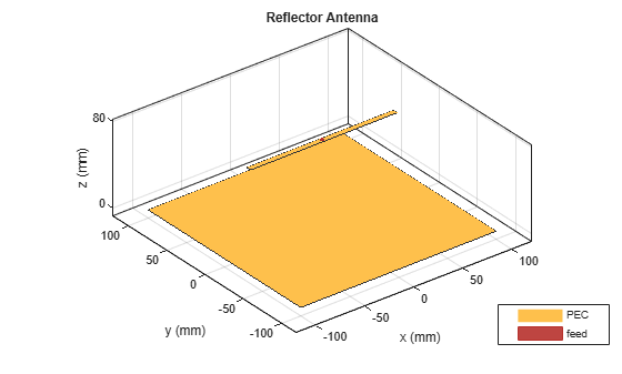
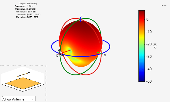
Looking at the radiation pattern, we see that there is some leakage below the ground. This is because of the size of the ground plane.
pattern(r, 1e9);
To prevent the leakage the ground plane must be made larger. However, by increasing the size of the ground plane the size of the mesh increases. The increase in mesh size increases the simulation time. Below is the mesh created for the structure above.
mesh(r);
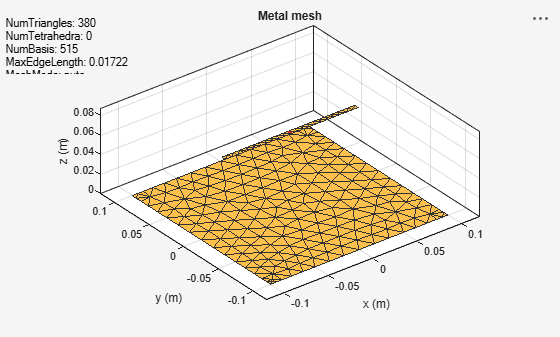
Increasing the ground plane size puts more triangles on the ground which will result in more simulation time.
Dipole Over Infinite Ground Plane
A simple way to prevent leakage below the ground plane is to make the ground plane infinite. This can be achieved by making either the GroundPlaneLength or GroundPlaneWidth or both to be infinite. In this case the ground plane is replaced by a blue sheet indicating that the ground plane is not made of metal.
r.GroundPlaneLength = inf;
figure
show(r)
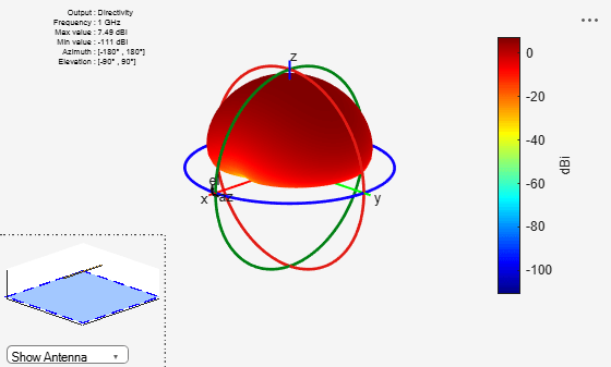
title("Dipole Antenna Over Infinite Ground Plane");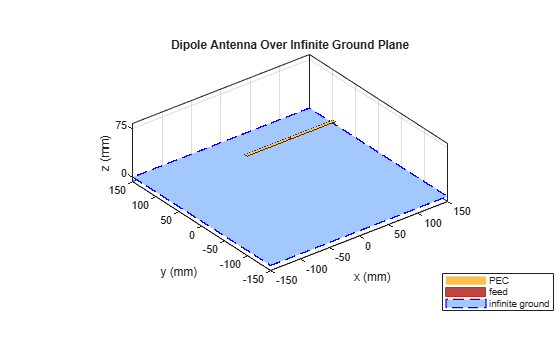
The pattern plot shows no leakage below the ground. This result can be used as a first pass to get a general idea of the antenna. The infinite ground plane can be replaced by a large finite one at the end to look for edge effects. Another interesting factor is the increase in maximum directivity value. As there no back lobe, all the energy is radiated above the ground plane, increasing the maximum directivity from 7.38 to 7.5dBi.
pattern(r,1e9);
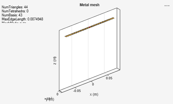
As mentioned before, the infinite ground plane is not meshed. The mesh for this structure shows only the mesh for the dipole element.
mesh(r);
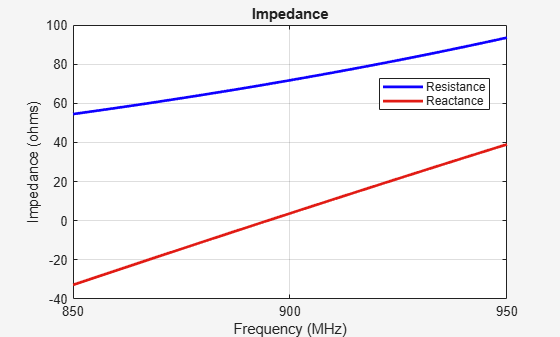
The impedance of the reflector with infinite ground plane looks similar to the one with the finite ground plane. The resonance value is shifted slightly from 880MHz for finite ground to 890MHz for the infinite case.
impedance(r,850e6:2e6:950e6);
Patch Antenna Array Over Infinite Ground
The concept of infinite ground becomes even more important for arrays. As the number of elements increase the size of the ground plane increases dramatically as the space on the ground between the elements also needs to be meshed. So choosing infinite ground plane for arrays is fairly common. Infinite ground planes in arrays are also called ground screens.
p = patchMicrostrip(GroundPlaneWidth=inf);
arr = rectangularArray(Element=p);
arr.RowSpacing = 0.075;
arr.ColumnSpacing = 0.1;
figure
show(arr)
title("2-by-2 Rectangular Array of Microstrip Patch Antenna Over Infinite Ground Plane");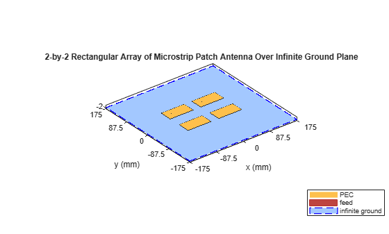
Above is the four element rectangular patch array on an infinite ground plane. The individual patches resonate around 1.75 GHz. Below is the pattern of the full array.
pattern(arr,1.75e9);

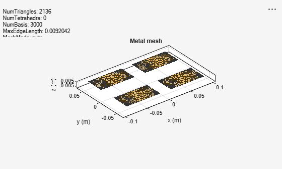
Again the plot shows that there is no radiation below the ground. The mesh that is used to solve the array is shown. As mentioned previously, the ground is not meshed so the overall size of the system is reduced resulting in faster computation time.
mesh(arr);
References
[1] Balanis, Constantine A. Antenna Theory: Analysis and Design. Fourth edition. Hoboken, New Jersey: Wiley, 2016.
See Also
Metasurface Antenna Modeling | Model Infinite Ground Plane for Balanced Antennas