이 페이지는 기계 번역을 사용하여 번역되었습니다. 영어 원문을 보려면 여기를 클릭하십시오.
CubeSat 모델링 및 시뮬레이션
모델을 생성하려면 CubeSat Vehicle 블록, 모델 템플릿 및 프로젝트를 사용하십시오. 여러 우주선을 모델링한 우주선 예제를 살펴보십시오. CubeSat Vehicle 블록은 한 번에 하나의 위성을 전파합니다. 여러 위성을 동시에 전파하려면 Orbit Propagator 블록을 사용하십시오. 최단 쿼터니언 회전을 계산하려면 Attitude Profile 블록을 사용하십시오.
우주선 모델링 및 시뮬레이션을 시작하는 데 도움을 드리기 위해, Aerospace Blockset™은 Simulink® 시작 페이지에 프로젝트와 모델을 제공하고 있습니다.
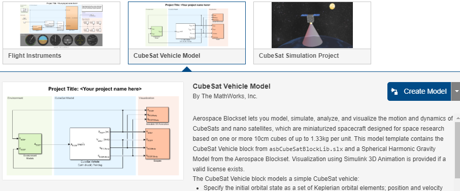
CubeSat 비행체 모델 템플릿 — CubeSat Vehicle 블록을 사용하여 CubeSat 궤적을 계산하고 시각화하는 방법을 보여주는 모델 템플릿(
CubeSat Simulation Project)입니다. Spherical Harmonic Gravity Model 블록은 궤도 계산에 사용되는 중력 포텐셜 소스로 활용됩니다. CubeSat Vehicle 블록에 설정된 사전 구성된 포인팅 모드가 자세를 제어합니다.CubeSat 시뮬레이션 프로젝트 — 제공된 프레임워크에 상세한 비행체 컴포넌트를 추가하여 Simulink에서 상세한 CubeSat 시스템 설계를 작성하는 방법을 보여주는, 바로 시뮬레이션에 활용할 수 있는 프로젝트(
CubeSat Simulation Project)입니다.CubeSat 모델 기반 시스템 엔지니어링 프로젝트 — 저궤도(LEO)에 위치한 1U CubeSat을 대상으로, Simulink에서 System Composer™ 및 Aerospace Blockset을 사용하여 우주 임무 아키텍처를 모델링하는 방법을 보여주는 시뮬레이션 준비 완료 프로젝트(
CubeSat Model-based System Engineering Project).
CubeSat 비행체 모델 템플릿
이 템플릿 모델은 Simulink 3D Animation™을 사용하여 시각화된 CubeSat Vehicle 블록을 포함하는, 바로 시뮬레이션할 수 있는 예제입니다.
CubeSat Vehicle Model 블록 대신 Vehicle Model 블록을 사용하는 방법을 보여주는 프로젝트는 CubeSat 시뮬레이션 프로젝트 항목을 참조하십시오.
CubeSat 비행체 모델 템플릿을 실행합니다. 명령줄에서
open('asbCubeSatVehicleTemplate.sltx')를 입력하십시오.Create Model을 클릭하십시오.
CubeSat Vehicle 블록은 간단한 CubeSat 비행체를 모델링한 것으로, CubeSat Vehicle 블록이 초기 궤도 상태를 케플러 궤도 요소 집합으로 사용하도록 구성되어 있으므로 이 블록을 그대로 사용할 수 있습니다.
이 모델은 Spherical Harmonic Gravity Model 블록을 사용하여 CubeSat의 비행체 중력을 제공합니다.
CubeSat에 대해 알아보기 위해 CubeSat Vehicle 블록 설정을 직접 실험해 보십시오.
블록의 CubeSat Orbit 탭에서, 선택적으로 Input method 파라미터를 사용하여 초기 궤도 상태를 다음의 조합으로 변경할 수 있습니다:
지구중심관성 좌표축에서의 위치 및 속도 벡터
ECEF(지구중심고정) 좌표축에서의 위치 및 속도 벡터
NED 프레임에서 표현된, ECEF를 기준으로 한 바디의 위도, 경도, 고도 및 속도
CubeSat Attitude 탭에서 CubeSat의 자세 제어를 정의하기 위한 정렬 벡터와 제약 벡터를 지정할 수 있습니다.
CubeSat 비행체는 먼저 주 정렬 벡터를 주 제약 벡터와 일치시킵니다. 그런 다음 CubeSat 비행체는 1차 정렬에 영향을 주지 않으면서 2차 정렬 벡터를 2차 제약 벡터와 가능한 한 가깝게 일치시키려고 시도합니다.
CubeSat의 Altitude 탭에서는 미리 설정된 "Earth (Nadir) Earth Pointing"(디폴트 값)과 "Sun Tracking" 자세 제어 모드 중에서 선택할 수도 있습니다.
Earth Orientation Parameters 탭에서는 ECI 좌표계와 ECEF 좌표계 간의 변환에 고차 지구 방향 파라미터를 포함하도록 블록을 설정할 수 있습니다.
모델을 실행하고 시뮬레이션하십시오.
CubeSat의 출력 신호를 확인하려면 Scopes 서브시스템을 더블 클릭하여 여러 개의 스코프를 엽니다.
유효한 Simulink 3D Animation 라이선스가 있다면, CubeSat Orbit Animation 창에서도 궤도를 시각화할 수 있습니다.
궤도 전파 모델의 사본을 저장하십시오. 이 모델은 임무 분석 라이브 스크립트에 사용할 수 있습니다.
CubeSat 비행체 모델 템플릿의 CubeSat Vehicle 블록은 미리 구성된 간단한 궤도 및 자세 제어 모드를 사용합니다. 자신이 직접 제작한 상세한 컴포넌트를 사용하여 CubeSat 비행체를 모델링하고 시뮬레이션하려면, Simulink 시작 페이지에 있는 CubeSat 시뮬레이션 프로젝트를 참고하시기 바랍니다. 자세한 내용은 CubeSat 시뮬레이션 프로젝트 항목을 참조하십시오.
CubeSat 시뮬레이션 프로젝트
이 프로젝트는 Simulink 3D Animation을 활용한 시각화 기능이 포함된, 바로 시뮬레이션할 수 있는 예제입니다. 이 예제에서는 CubeSat Vehicle 블록 대신 Vehicle Model 서브시스템을 사용합니다.
System Composer를 사용하여 우주 임무 아키텍처도 모델링하는 모델에 대해서는 CubeSat 모델 기반 시스템 공학 프로젝트 항목을 참조하십시오.
CubeSat 시뮬레이션 프로젝트를 시작하십시오. 명령줄에서
open('asbCubeSatSimulationProject.sltx')를 입력하십시오.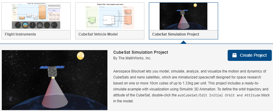
Create Project를 클릭하고 안내에 따라 진행하십시오.
Vehicle Model 서브시스템은 그대로 사용할 수 있는 CubeSat 비행체를 모델링합니다.
보다 정교한 위성 모델을 직접 만들려면 Vehicle Model 프레임워크를 활용해 보십시오. 예를 들어, 액추에이터 서브시스템에 기본으로 포함된 완벽한 추진기 모델을, 직접 만든 보다 현실적인 추진기나 반작용 휠 모델로 대체할 수 있습니다.
CubeSat의 궤도 궤적과 자세를 변경하려면, Mission Configuration 섹션에서 Edit Initial Orbit and Attitude 블록을 더블 클릭하십시오. 이 파라미터들은 CubeSat Vehicle 블록의 해당 파라미터와 동일한 목적을 가집니다.
모델을 실행하고 시뮬레이션하십시오.
CubeSat의 출력 신호를 확인하려면 Scopes 서브시스템을 더블 클릭하여 여러 개의 스코프를 엽니다.
Simulink 3D Animation 라이선스가 있다면, 애니메이션 창에서 궤도를 시각화할 수도 있습니다. Visualization 서브시스템을 더블 클릭한 다음 Open Simulink 3D Animation window 버튼을 클릭합니다.
CubeSat Orbit Animation 창이 열립니다.
CubeSat 모델 기반 시스템 공학 프로젝트
CubeSat 모델 기반 시스템 공학(MBSE) 프로젝트는 System Composer와 Aerospace Blockset을 사용하여 우주 임무 아키텍처를 모델링하는 방법을 보여주는 시뮬레이션 준비가 완료된 예제입니다. 이 프로젝트는 서브시스템 모델을 재사용하기 위해 CubeSat 시뮬레이션 프로젝트를 참조한 다음, System Composer 아키텍처 계층을 추가하고, 시스템 요구 사항을 아키텍처 내의 컴포넌트에 연결하며, Simulink Test™를 통해 최상위 임무 요구 사항을 검증합니다. 이 프로젝트는 Simulink 3D Animation, Aerospace Toolbox 위성 시나리오 및 Mapping Toolbox™를 사용하여 결과를 시각화합니다.
명령줄에서
open('asbCubeSatMBSEProject.sltx')를 입력하고, Create Project를 클릭한 다음, 안내에 따라 진행하십시오.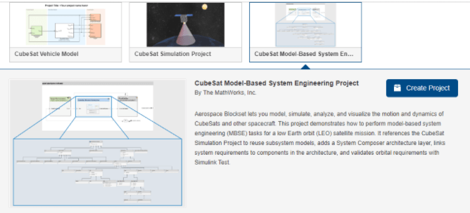
MATLAB® 명령 창에서 Projects Shortcut 탭을 선택한 다음, MBSE Template Overview를 클릭합니다.
이 템플릿 개요에서는 프로젝트에 대해 설명하고, 우주 임무 아키텍처를 모델링하는 방법을 다룹니다.
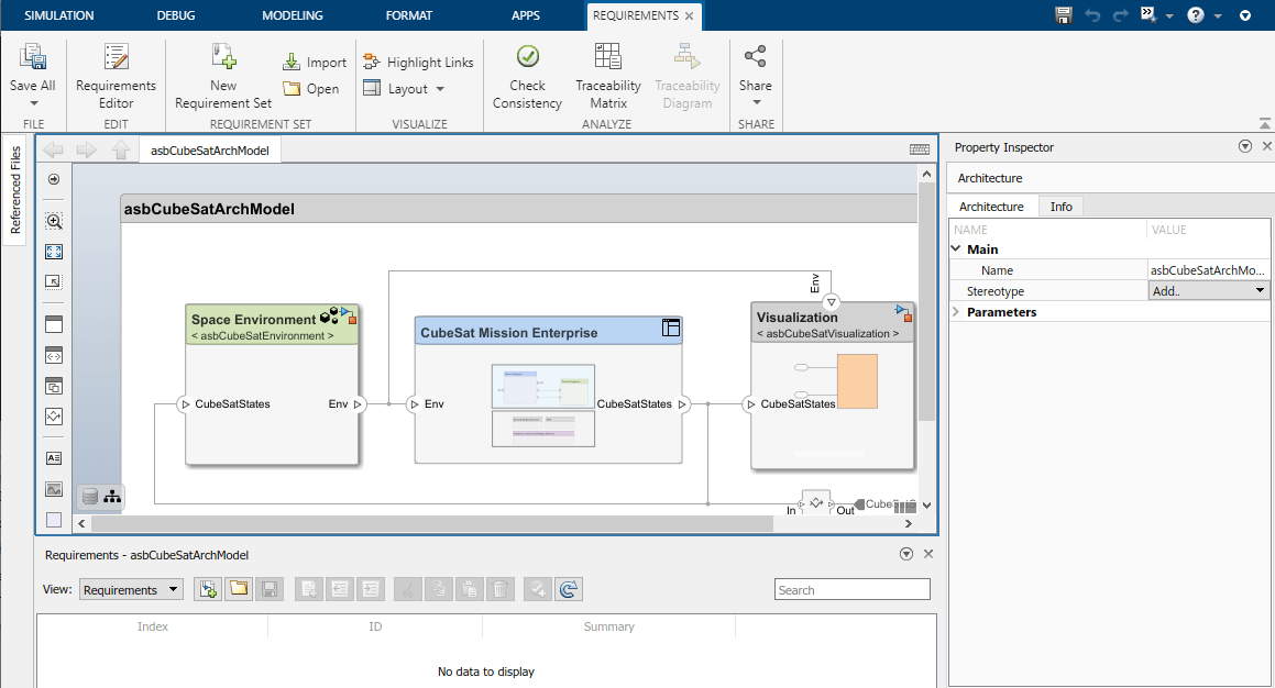
이 개요를 통해
asbCubeSatArchModel아키텍처를 살펴보고, System Composer를 사용하여 아키텍처를 확장하는 방법을 알아보십시오.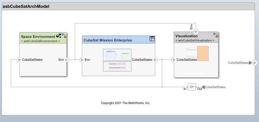
이 프로젝트는 System Composer 내에서 아키텍처를 정의하는 데 도움이 됩니다. 이 예시의 아키텍처는 국제시스템공학협의회(INCOSE) 우주시스템 실무그룹(SSWG)이 개발한 CubeSat 참조 모델(CRM)을 기반으로 합니다.
컴포넌트의 내부 구성 요소를 보려면 해당 컴포넌트를 더블 클릭하십시오. 예를 들어, 해당 임무의 아키텍처 모델을 보려면
CubeSat Mission Enterprise를 더블 클릭하십시오.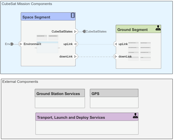
이 모델은 큰 규모의 임무를 모델링하는 System Composer 컴포넌트들로 이루어져 있습니다.
MBSE Template Overview를 사용하여 프로젝트를 둘러보고, System Composer 요소를 활용해 우주 임무 아키텍처를 모델링하는 방법을 알아보십시오.
System Composer를 사용하여 다음 작업을 수행할 수 있습니다.
스테레오타입을 사용하여 요소에 도메인별 메타데이터를 추가함으로써 아키텍처 요소를 확장합니다. 컴포넌트, 커넥터, 포트 및 기타 아키텍처 요소에 스테레오타입을 적용하여 이러한 요소들에 공통적인 속성 집합을 부여합니다. 프로파일에서 스테레오타입을 확인, 수정하거나 새로 추가하려면 Modeling 탭에서 Profile Editor를 클릭한 다음 스테레오타입 프로파일을 선택하십시오. 이 예제를 보려면
CubeSatProfile.xml프로파일을 여십시오.
프로파일을 수정하거나, 새로운 프로파일을 추가하거나, 컴포넌트에 새로운 프로파일을 적용할 수 있습니다.
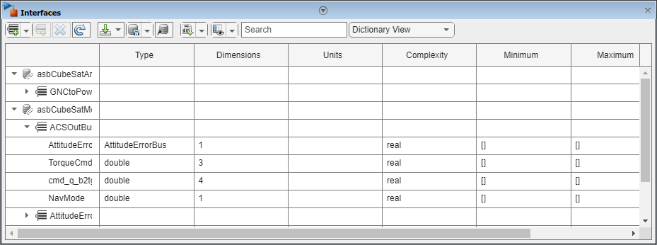
인터페이스를 사용하여 포트를 통해 흐르는 정보의 종류를 정의합니다. 포트의 인터페이스를 확인, 편집하거나 새 인터페이스를 추가하려면 Modeling 탭에서 Interface Editor를 클릭한 다음 인터페이스를 선택하십시오. 예를 들어, asbCubeSatModelData.sldd > ACSOutBus를 선택하십시오.
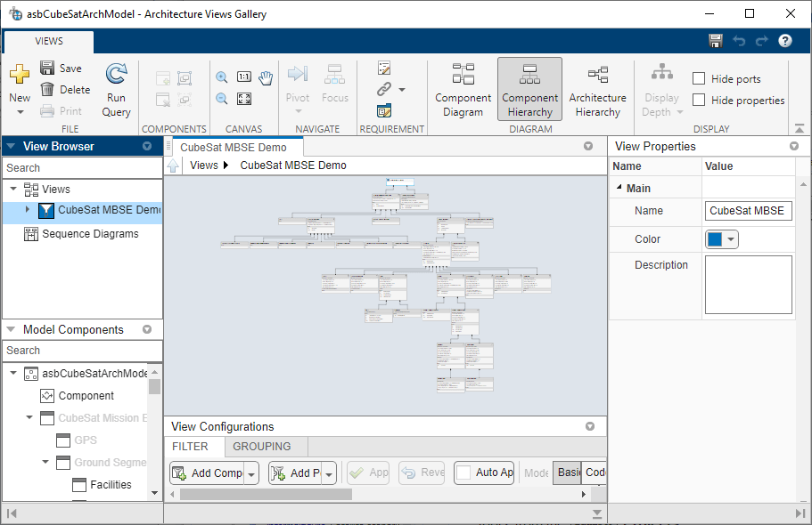
Views > Architecture Views를 클릭하고 CubeSat MBSE Demo와 같은 뷰를 선택하여 아키텍처 뷰를 통해 시스템을 시각화합니다.
추적 가능성을 확보하기 위해, 함수 요구사항을 컴포넌트에 할당함으로써 시스템 요구사항 간의 연관성을 설정합니다. 모델의 Apps 탭에서 Requirements Manager를 선택하십시오.
아키텍처를 모델에 연결하거나 아키텍처를 시뮬레이션하는 등 이 프로젝트를 활용하는 방법에 대한 자세한 내용은 MBSE Template Overview를 참조하십시오.
최상위 임무 요구 사항을 검증하려면 Simulink Test를 사용하십시오.
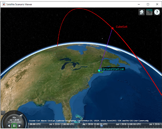
위성 시나리오 툴을 사용하여 CubeSat의 임무 분석을 수행하는 방법을 이해하려면, MATLAB 명령 창에서 Projects Shortcut 탭을 선택한 후 Analyze with Satellite Scenario를 클릭하십시오.
유틸리티 함수
Aerospace Toolbox는 좌표 변환을 위한 유틸리티 함수를 제공합니다. 이 함수들을 사용하면 CubeSat Vehicle 블록의 다양한 초기 조건 모드 간을 전환할 수 있습니다.
| 동작 | 함수 |
|---|---|
지구중심관성 좌표계, 평균 적도 좌표계, 평균 춘분점 좌표계에서의 위치 및 속도 벡터 계산 | |
ECEF(지구중심고정) 좌표계에서의 위치, 속도 및 가속도 벡터 계산 | |
그리니치 평균시와 겉보기 항성시 계산 | |
지구중심 적도 위치 및 속도 벡터를 사용하여 케플러 궤도 요소 계산 | |
케플러 궤도 요소를 사용하여 지구 중심 적도 좌표계에서 위치 벡터와 속도 벡터 계산 |
참고 문헌
[1] Vallado, D. A. Fundamentals of Astrodynamics and Applications. New York: McGraw-Hill, 1997.
참고 항목
블록
- Attitude Profile (Nadir Pointing) | CubeSat Vehicle Earth (Nadir) Pointing | Orbit Propagator Kepler (unperturbed)