이 번역 페이지는 최신 내용을 담고 있지 않습니다. 최신 내용을 영문으로 보려면 여기를 클릭하십시오.
NR 위상 잡음 모델링 및 보상
이 예제에서는 5G OFDM 시스템에서 위상 잡음의 영향을 보여주고 CPE(공통 위상 오차) 보상에 PT-RS(위상 추적 기준 신호)를 사용하는 방법을 보여줍니다. 이 예제에서는 CPE 보상이 있는 경우와 없는 경우의 EVM(오류 벡터 크기)과 BER(비트 오류율)을 측정합니다.
소개
5G NR에서, 3GPP는 발진기 잡음을 처리하기 위해 PT-RS(위상 추적 기준 신호)라는 새로운 기준 신호를 도입합니다. 발진기에서 발생한 잡음은 정보 신호의 위상 변조로 이어져 정보 신호의 주파수 스펙트럼과 타이밍 속성에 상당한 변화를 초래합니다. 발진기와 관련된 이와 같은 현상을 위상 잡음이라고 합니다. 국부 발진기에서 발생하는 위상 잡음은 위상 잡음의 파워 스펙트럼 밀도에 따라 밀리미터파(mmWave) 주파수에서 상당한 성능 저하를 초래합니다. 위상 잡음으로 인해 CPE와 ICI(반송파 간 간섭)가 발생합니다. CPE는 각 부반송파에서 수신된 심볼의 동일한 회전으로 이어집니다. ICI는 부반송파 간의 직교성 손실로 이어집니다. 주파수 영역에서의 PT-RS의 분포 구조 때문에, 이 예제는 PT-RS를 주로 사용하여 CPE가 시스템 성능에 미치는 영향을 추정하고 최소화합니다. 이 예제에서는 PDSCH(physical downlink shared channel)로 구성된 파형에 위상 잡음을 적용하고 CPE 보상이 없는 경우와 있는 경우의 EVM과 BER의 변화를 보여줍니다. 아래 그림은 이 예제에서 구현된 처리 체인을 보여줍니다.

위상 잡음 모델링
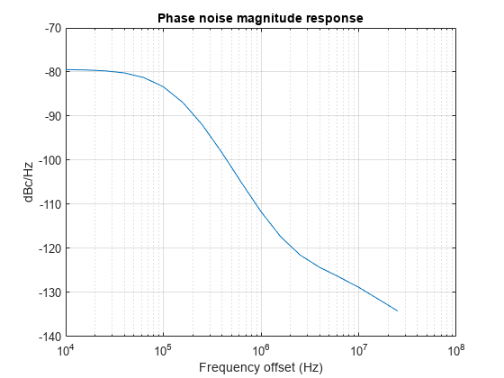
발진기 파워 스펙트럼 밀도는 위상 잡음을 모델링합니다. 이 예제에서는 3GPP TR 38.803: Radio Frequency (RF) and co-existence aspects의 Section 6.1.10에 설명된 다중 극점-영점 모델을 사용하여 발진기의 파워 스펙트럼 밀도를 근사합니다. System object™ hNRPhaseNoise는 TR 38.803에서 권장되는 위상 잡음 PSD 프로파일을 모델링합니다. Model 속성을 '29.55', '45' 또는 '70'으로 설정하면 각각 29.55GHz, 45GHz 또는 70GHz에서 작동하는 모델에 대해 설정된 파라미터 세트를 사용할 수 있습니다. 지정된 CarrierFrequency 속성값에 가장 가까운 모델을 지정하려면 Model 속성을 'Auto'로 설정하십시오.
이 예제에서는 50MHz의 송신 대역폭에 대해 60kHz의 부반송파 간격을 갖는 반송파를 사용합니다.
% Configure carrier
carrier = nrCarrierConfig;
carrier.SubcarrierSpacing = 60;
carrier.CyclicPrefix = 'normal';
carrier.NSizeGrid = 66;

% Set the operating frequency
Fc = 30e9; % Hz

% Get the sample rate
ofdmInfo = nrOFDMInfo(carrier);
sr = ofdmInfo.SampleRate;

% Model phase noise
pnoise = hNRPhaseNoise(Fc,sr,MinFrequencyOffset=1e4,...
    RandomStream="mt19937ar with seed"); % dBc/Hz, Model='Auto'

% Visualize spectrum mask of phase noise
visualize(pnoise);
PDSCH 구성하기
이 예제에서는 변조 방식을 '64QAM'으로 설정하고 계층 개수를 1로 설정하여 전체 반송파를 점유하는 PDSCH를 구성합니다. 이 예제는 기본적으로 단일 계층과 코딩되지 않은 랜덤 비트의 단일 코드워드로 구성됩니다.
% Set PDSCH parameters
pdsch = nrPDSCHConfig;
pdsch.PRBSet = 0:carrier.NSizeGrid-1;
pdsch.SymbolAllocation = [0 14];
pdsch.Modulation = '64QAM';
pdsch.NumLayers = 1;
pdsch.MappingType = 'A';
pdsch.NID = 1;
pdsch.RNTI = 2;

% Set DM-RS parameters
pdsch.DMRS.DMRSConfigurationType = 1;
pdsch.DMRS.DMRSTypeAPosition = 2;
pdsch.DMRS.DMRSAdditionalPosition = 0;
pdsch.DMRS.DMRSLength = 1;
pdsch.DMRS.DMRSPortSet = [];
pdsch.DMRS.NumCDMGroupsWithoutData = 1;
pdsch.DMRS.NIDNSCID = 1;
pdsch.DMRS.NSCID = 0;

% Set PT-RS parameters
pdsch.EnablePTRS = 1;
pdsch.PTRS.TimeDensity = 1;
pdsch.PTRS.FrequencyDensity = 2;
pdsch.PTRS.REOffset = '00';
pdsch.PTRS.PTRSPortSet = [];
파형 생성하기
파형은 2개 프레임에 대해 생성되며, simParameters 구조체의 필드 NumFrames는 파형의 프레임 수를 제어합니다. 관련 단계는 다음과 같습니다.
PDSCH의 비트 용량으로 랜덤 코드워드 생성
랜덤 코드워드에 대한 PDSCH 심볼을 얻어 그리드에 매핑
DM-RS 심볼을 생성하고 그리드에 매핑
PT-RS 심볼을 생성하고 그리드에 매핑
모든 프레임의 전체 그리드에 대해 OFDM 변조 수행
% Number of frames to generate the waveform
simParameters = [];
simParameters.NumFrames = 2;

% Get the number of slots in the waveform and number of symbols in a slot
numSlots = carrier.SlotsPerFrame*simParameters.NumFrames;
nSlotSymb = carrier.SymbolsPerSlot;

% Initialize the grid for specified number of frames
txGrid = zeros(carrier.NSizeGrid*12,nSlotSymb*numSlots,pdsch.NumLayers);

% Processing loop
txbits = [];
rng('default')
for slotIdx = 0:numSlots - 1
    % Set slot number
    carrier.NSlot = slotIdx;

    % Get PDSCH indices and structural information
    [pdschInd,pdschIndicesInfo] = nrPDSCHIndices(carrier,pdsch);

    % Generate random codeword(s)
    numCW = pdsch.NumCodewords; % Number of codewords
    data = cell(1,numCW);
    for i = 1:numCW
        data{i} = randi([0 1],pdschIndicesInfo.G(i),1);
        txbits = [txbits; data{i}]; %#ok<AGROW>
    end

    % Get modulated symbols
    pdschSym = nrPDSCH(carrier,pdsch,data);

    % Get DM-RS symbols and indices
    dmrsSym = nrPDSCHDMRS(carrier,pdsch);
    dmrsInd = nrPDSCHDMRSIndices(carrier,pdsch);

    % Get PT-RS symbols and indices
    ptrsSym = nrPDSCHPTRS(carrier,pdsch);
    ptrsInd = nrPDSCHPTRSIndices(carrier,pdsch);

    % Resource element mapping to slot grid
    slotGrid = nrResourceGrid(carrier,pdsch.NumLayers);
    slotGrid(pdschInd) = pdschSym;
    slotGrid(dmrsInd) = dmrsSym;
    slotGrid(ptrsInd) = ptrsSym;

    % Generate txGrid for all frames by mapping slotGrid at respective
    % locations
    txGrid(:,slotIdx*nSlotSymb+1:(slotIdx+1)*(nSlotSymb),:) = slotGrid;
end

% Perform OFDM modulation
carrier.NSlot = 0; % Reset the slot number to 0 for OFDM modulation
txWaveform = nrOFDMModulate(carrier,txGrid);
위상 잡음 적용하기
위상 잡음을 송신되는 파형에 적용합니다. 위상 잡음의 영향을 명확히 관찰하기 위해, 이 예제에서는 위상 잡음 외의 다른 열 잡음이나 채널 모델을 적용하지 않습니다. 이 예제에서는 모든 계층에 동일한 위상 잡음을 적용합니다.
rxWaveform = pnoise(txWaveform);
수신기
수신기는 이퀄라이징된 PDSCH 심볼과 디코딩된 비트를 반환하기 전에 다음 단계를 수행합니다.
타이밍 동기화
OFDM 복조
채널 추정
이퀄라이제이션
CPE 추정 및 정정
PDSCH 디코딩
CPE 추정 및 정정 단계에서 수신기는 simParameters 구조체의 논리 필드 CompensateCPE를 사용합니다. 이 예제에서는 전파(propagation) 채널을 사용하지 않기 때문에 타이밍 동기화, 채널 추정, 이퀄라이제이션 단계가 꼭 필요하지는 않습니다. 그러나 채널을 도입하는 경우 이러한 단계는 위상 잡음 효과를 조사하는 데 도움이 됩니다.
이 예제에서는 CPE 보상이 있는 경우와 없는 경우의 이퀄라이징된 성상도 심볼, EVM, 비트 오류율을 보여줍니다.
사례 1: CPE 보상이 없는 경우
CPE 보상을 비활성화하려면 simParameters 구조체의 필드 CompensateCPE를 0으로 설정합니다.
simParameters.CompensateCPE = 0;
[eqSymbols,rxbits] = practicalReceiver(carrier,pdsch,simParameters,rxWaveform);
refSymbols = getConstellationPoints(pdsch);
% Display the constellation diagram
figure
plot(eqSymbols,'.')
hold on
plot(refSymbols,'+')
title('Equalized Symbols Constellation Without CPE Compensation')
grid on
xlabel('In-Phase')
ylabel('Quadrature')

% Display RMS EVM
evm = comm.EVM('ReferenceSignalSource','Estimated from reference constellation','ReferenceConstellation',refSymbols);
fprintf('RMS EVM (in percent) for equalized symbols without CPE compensation: %f%% \n',evm(eqSymbols))
RMS EVM (in percent) for equalized symbols without CPE compensation: 4.637565%
% Display bit error rate
errorRate = nnz(rxbits-txbits)/numel(txbits);
fprintf('Bit error rate without CPE compensation: %f \n',errorRate)
Bit error rate without CPE compensation: 0.000019
사례 2: CPE 보상이 있는 경우
CPE 보상을 활성화하려면 simParameters 구조체의 필드 CompensateCPE를 1로 설정합니다. PT-RS를 사용하여 슬롯의 모든 OFDM 심볼 위치에서 CPE를 추정합니다. PT-RS OFDM 심볼 범위 내의 OFDM 심볼 위치에서 CPE를 정정합니다.
simParameters.CompensateCPE = 1;
[eqSymbolsCPE,rxbitsCPE] = practicalReceiver(carrier,pdsch,simParameters,rxWaveform);
% Display the constellation diagram
figure
plot(eqSymbolsCPE,'.')
hold on
plot(refSymbols,'+')
title('Equalized Symbols Constellation With CPE Compensation')
grid on
xlabel('In-Phase')
ylabel('Quadrature')
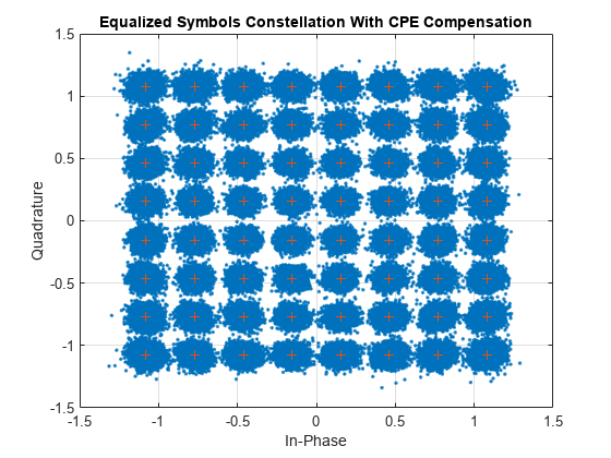
% Display RMS EVM
fprintf('RMS EVM (in percent) for equalized symbols with CPE compensation: %f%% \n',evm(eqSymbolsCPE))
RMS EVM (in percent) for equalized symbols with CPE compensation: 3.982680%
% Display bit error rate
errorRateCPE = nnz(rxbitsCPE-txbits)/numel(txbits);
fprintf('Bit error rate with CPE compensation: %f \n',errorRateCPE)
Bit error rate with CPE compensation: 0.000000
심층 탐구
위상 잡음의 영향을 시각화하기 위해 반송 주파수, 부반송파 간격, 리소스 블록 수, 변조 방식, 프레임 수를 변경해 봅니다.
다양한 구성으로 CPE 보상의 효과를 분석하기 위해 PT-RS의 시간과 주파수 밀도를 변경해 봅니다.
열 잡음과 채널 모델을 포함시켜 위상 잡음의 영향을 시각화해 봅니다.
요약
이 예제에서는 위상 잡음의 영향을 보여주고 PT-RS로 CPE를 추정하고 보정하는 방법을 보여줍니다. 또한 CPE 보상이 EVM을 감소시키고 비트 오류율을 개선한다는 것도 보여줍니다. 표시된 성상도 플롯은 mmWave 단위의 주파수에서 매우 큰 ICI를 보여주며, 이는 CPE 보상 외에 ICI 보상을 수행해야 함을 의미합니다.
로컬 함수
function [eqSymbols,rxbits] = practicalReceiver(carrier,pdsch,params,rxWaveform)
% Returns equalized modulated symbols after performing the timing
% estimation, OFDM demodulation, channel estimation, MMSE equalization,
% CPE estimation and correction, and PDSCH decoding.

    % Get the current slot number, number of slots, number of symbols
    % per slot, and total number of symbols
    nSlot = carrier.NSlot;
    numSlots = carrier.SlotsPerFrame*params.NumFrames;
    nSlotSymb = carrier.SymbolsPerSlot;
    numTotalSymbols = numSlots*nSlotSymb;

    % Get reference grid with DM-RS symbols
    dmrsSymCell = cell(1,numSlots);
    dmrsIndCell = cell(1,numSlots);
    refGrid = zeros(carrier.NSizeGrid*12,numTotalSymbols,pdsch.NumLayers);
    for NSlot = 0:numSlots-1
        carrier.NSlot = NSlot;
        slotGrid = nrResourceGrid(carrier,pdsch.NumLayers);
        dmrsSymCell{NSlot+1} = nrPDSCHDMRS(carrier,pdsch);
        dmrsIndCell{NSlot+1} = nrPDSCHDMRSIndices(carrier,pdsch);
        slotGrid(dmrsIndCell{NSlot+1}) = dmrsSymCell{NSlot+1};
        refGrid(:,NSlot*nSlotSymb+1:(NSlot+1)*(nSlotSymb),:) = slotGrid;
    end

    % Perform timing estimation and correction
    carrier.NSlot = nSlot;
    offset = nrTimingEstimate(carrier,rxWaveform,refGrid);
    waveformSync = rxWaveform(1+offset:end,:);

    % Perform OFDM demodulation on the received data to recreate the
    % resource grid, including padding in the event that practical
    % synchronization results in an incomplete slots being demodulated
    rxGrid = nrOFDMDemodulate(carrier,waveformSync);
    [K,L,R] = size(rxGrid);
    if (L < numTotalSymbols)
        rxGrid = cat(2,rxGrid,zeros(K,numTotalSymbols-L,R));
    end

    % Declare storage variables
    eqSymbols = [];  % equalized symbols for constellation plot
    rxbits = [];

    for NSlot = 0:numSlots-1
        % Extract grid for current slot
        currentGrid = rxGrid(:,NSlot*nSlotSymb+(1:nSlotSymb),:);

        % Get the PDSCH resources
        carrier.NSlot = NSlot;
        dmrsSymbols = dmrsSymCell{NSlot+1};
        dmrsIndices = dmrsIndCell{NSlot+1};
        ptrsSymbols = nrPDSCHPTRS(carrier,pdsch);
        ptrsIndices = nrPDSCHPTRSIndices(carrier,pdsch);
        [pdschIndices,pdschIndicesInfo] = nrPDSCHIndices(carrier,pdsch);

        % Channel estimation
        [estChannelGrid,noiseEst] = nrChannelEstimate(currentGrid,dmrsIndices,dmrsSymbols,"CDMLengths",pdsch.DMRS.CDMLengths);

        % Get PDSCH resource elements from the received grid
        [pdschRx,pdschHest] = nrExtractResources(pdschIndices,currentGrid,estChannelGrid);

        % Equalization
        pdschEq = nrEqualizeMMSE(pdschRx,pdschHest,noiseEst);

        % Common phase error (CPE) estimation and correction
        if params.CompensateCPE
            % Initialize temporary grid to store equalized symbols
            tempGrid = nrResourceGrid(carrier,pdsch.NumLayers);

            % Extract PT-RS symbols from received grid and estimated
            % channel grid
            [ptrsRx,ptrsHest,~,~,~,ptrsLayerIndices] = nrExtractResources(ptrsIndices,currentGrid,estChannelGrid,tempGrid);

            % Equalize PT-RS symbols and map them to tempGrid
            ptrsEq = nrEqualizeMMSE(ptrsRx,ptrsHest,noiseEst);
            tempGrid(ptrsLayerIndices) = ptrsEq;

            % Estimate the residual channel at the PT-RS locations in
            % tempGrid
            cpe = nrChannelEstimate(tempGrid,ptrsIndices,ptrsSymbols);

            % Sum estimates across subcarriers, receive antennas, and
            % layers. Then, get the CPE by taking the angle of the
            % resultant sum
            cpe = angle(sum(cpe,[1 3 4]));

            % Map the equalized PDSCH symbols to tempGrid
            tempGrid(pdschIndices) = pdschEq;

            % Correct CPE in each OFDM symbol within the range of reference
            % PT-RS OFDM symbols
            if numel(pdschIndicesInfo.PTRSSymbolSet) > 0
                symLoc = pdschIndicesInfo.PTRSSymbolSet(1)+1:pdschIndicesInfo.PTRSSymbolSet(end)+1;
                tempGrid(:,symLoc,:) = tempGrid(:,symLoc,:).*exp(-1i*cpe(symLoc));
            end

            % Extract PDSCH symbols
            pdschEq = tempGrid(pdschIndices);
        end

        % Store the equalized symbols and output them for all the slots
        eqSymbols = [eqSymbols; pdschEq]; %#ok<AGROW>

        % Decode the PDSCH symbols and get the hard bits
        eqbits = nrPDSCHDecode(carrier,pdsch,pdschEq);
        for i = 1:numel(eqbits)
            rxbits = [rxbits; double(eqbits{i}<0)]; %#ok<AGROW>
        end

    end

end

function sym = getConstellationPoints(pdsch)
%getConstellationPoints Constellation points
%   SYM = getConstellationPoints(PDSCH) returns the constellation points
%   SYM based on modulation schemes provided in PDSCH configuration object.

    sym = [];
    modulation = string(pdsch.Modulation);  % Convert modulation scheme to string type
    ncw = pdsch.NumCodewords;               % Number of codewords
    if ncw == 2 && isscalar(modulation)
        modulation(end+1) = modulation(1);
    end
    % Get the constellation points
    for cwIndex = 1:ncw
        qm = strcmpi(modulation(cwIndex),{'QPSK','16QAM','64QAM','256QAM'})*[2 4 6 8]';
        sym = [sym; nrSymbolModulate(int2bit((0:2^qm-1)',qm),modulation(cwIndex))]; %#ok<AGROW>
    end

end