Model Hybrid Beamforming with CDL Channel
R2026bThis example shows how to apply digital and analog beamforming to a 5G New Radio (NR) physical downlink shared channel (PDSCH) link by using a CDL channel.
Introduction
Fully digital beamforming techniques equip one radio frequency (RF) chain for each antenna element. This architecture presents challenges in terms of power consumption, cost, and hardware complexity, especially at millimeter-wave frequencies. Hybrid beamforming combines analog and digital processing to optimize performance while reducing the number of RF chains, power usage, and hardware requirements. This approach enables flexible beam management and spatial multiplexing of multiple simultaneous data streams. This example illustrates how to combine digital and analog beamforming techniques in a 5G NR PDSCH transmission.
Two widely considered approaches are the fully and partially connected architectures. In the fully connected architecture, each RF chain connects to all elements of an antenna array. In the partially connected architecture, each RF chain connects to a subset of antenna elements. This example demonstrates a partially connected architecture by using fixed rectangular subarrays of equal size.
To reduce the RF chain complexity for FR2 and to support spatial multiplexing, the transmitter uses an analog and a digital beamforming stage. During the analog stage, the transmitter selects a directional beam. During the digital stage, the transmitter computes a digital precoder from the effective channel and applies it to the transmitted layers. This example adopts a semi-static hybrid beamforming approach. First, it updates the analog beam on a slow timescale, then updates the digital precoder over the lower-dimensional effective channel more frequently.
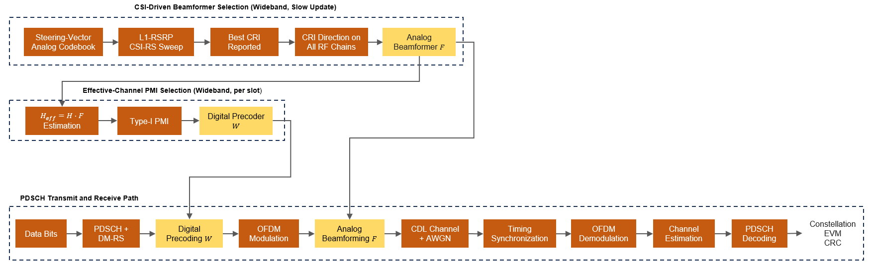
This figure shows the implemented processing chain. The example performs a Layer-1 reference signal received power (L1-RSRP) channel state information reference signal (CSI-RS) beam measurement over a steering-vector codebook. It then selects a wideband analog beamformer from the reported measurements. Next, the example computes a Type-I precoding matrix indicator (PMI)-based digital precoder, , from the effective channel, , where is the MIMO channel. Finally, the example applies and to a PDSCH transmission, propagates the waveform through the CDL channel, and processes the received signal to decode the data. The example then checks the decoded transport block against its cyclic redundancy check (CRC) to confirm error-free reception.
Modeling Scope and Assumptions
This example models the signal-processing structure of hybrid beamforming under these assumptions:
The hybrid beamforming uses two separate stages: an analog stage updated once per CSI-RS reporting period and a slot-based digital stage. Both stages use wideband CSI.
The analog stage uses an L1-RSRP CSI-RS beam sweep. It selects the beamformer corresponding to the strongest reported resource indicator (CRI) RSRP, so all subarrays point in the same direction. The digital stage uses a Type-I single-panel PMI.
The example models one CSI-RS sweep and one PMI report immediately before the PDSCH slot. For the initial beam-management steps, see the NR SSB Beam Sweeping and NR Downlink Transmit-End Beam Refinement Using CSI-RS examples.
Simulation Parameters
Set the signal-to-noise ratio (SNR) for the simulation. The SNR for each layer and resource element (RE) accounts for the signal and noise across all antennas. For an explanation of the SNR definition that this example uses, see the SNR Definition Used in Link Simulations example.
% Reset the global random number generator for reproducible results
rng(0,"twister");

simParameters = struct();
simParameters.SNRIn = 10; % dB
Channel Estimator Configuration
The logical variable PerfectChannelEstimator controls the channel estimation behavior. When you set this variable to true, the simulation uses perfect channel estimation. When you set it to false, the simulation uses practical channel estimation based on the values of the received PDSCH demodulation reference signal (DM-RS).
simParameters.PerfectChannelEstimator =  true;
true;Carrier and PDSCH Configuration
Set a 100 MHz bandwidth FR2 carrier with a 120 kHz subcarrier spacing.
% SCS carrier parameters
simParameters.Carrier = nrCarrierConfig;       % Carrier resource grid configuration
simParameters.Carrier.NSizeGrid = 66;          % Bandwidth in number of resource blocks. 66 RBs at 120 kHz SCS is about 95.04 MHz BW (FR2 channel BW = 100 MHz)
simParameters.Carrier.SubcarrierSpacing = 120; % 15, 30, 60, 120, 480, 960 (kHz)
Specify a full-band slot-wise PDSCH transmission. The example sets the number of layers, modulation scheme, and target code rate of the PDSCH transmission based on the received CSI report.
simParameters.PDSCH = nrPDSCHConfig;

% Define PDSCH time allocation in a slot (Mapping Type A)
simParameters.PDSCH.SymbolAllocation = [0 simParameters.Carrier.SymbolsPerSlot]; % Starting symbol and number of symbols of each PDSCH allocation

% Define PDSCH frequency resource allocation per slot to be full grid
simParameters.PDSCH.PRBSet = 0:simParameters.Carrier.NSizeGrid-1;
Antenna Array Configuration
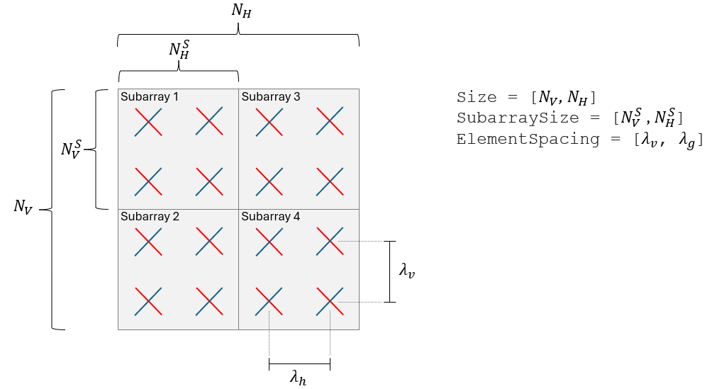
Configure rectangular antenna arrays by specifying their size and number of polarizations. In this example, the antenna array consists of nonoverlapping rectangular subarrays of equal size. You can configure the number of vertical and horizontal elements of the antenna array (, ) and of the subarrays (, ). The antenna array and subarray sizes must be compatible to fit an integer number of subarrays in the array, that is, and must be integers. This diagram illustrates the partitioning of a 4-by-4 antenna array into 2-by-2 subarrays:
simParameters.TransmitAntennaArray.Size = [4 4];               % Number of vertical and horizontal antenna elements in array
simParameters.TransmitAntennaArray.SubarraySize = [2 2];       % Number of vertical and horizontal elements in subarray
simParameters.TransmitAntennaArray.ElementSpacing = [0.5 0.5]; % Vertical and horizontal distance between antenna elements (wavelengths)
simParameters.TransmitAntennaArray.NumPolarizations = 2;       % Number of polarizations

simParameters.ReceiveAntennaArray.Size = [2 1];                % Number of vertical and horizontal antenna elements
simParameters.ReceiveAntennaArray.ElementSpacing = [0.5 0.5];  % Vertical and horizontal distance between antenna elements (wavelengths)
simParameters.ReceiveAntennaArray.NumPolarizations = 2;        % Number of polarizations
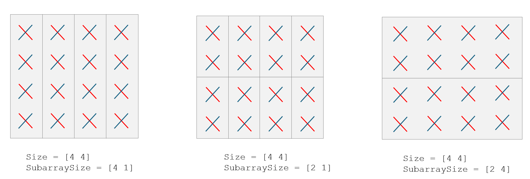
This diagram illustrates three different ways of partitioning a 4-by-4 antenna array into 4 vertical subarrays of size 4-by-1 (left), 8 vertical subarrays of size 2-by-1 (center), and 2 horizontal subarrays of size 2-by-4 elements (right):
To configure single-input single-output (SISO) transmissions with single-polarized antenna elements, set the antenna array and subarray sizes to [1 1] and the number of polarizations to 1.
RF Connections to Antenna Elements
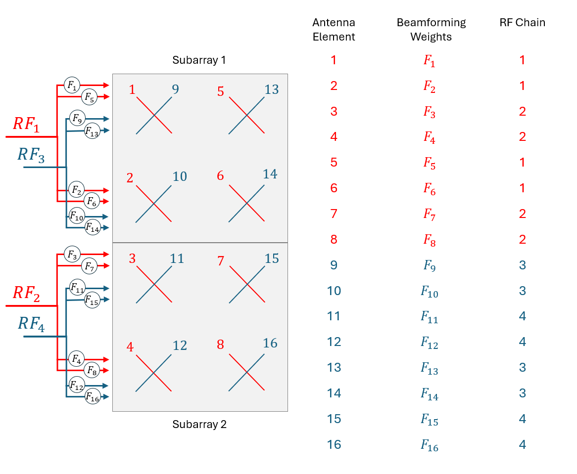
Configure how each RF chain connects to each antenna element within a subarray. Each antenna subarray has two polarizations, and each polarization is fully connected to a single RF chain. This example calculates the connections between the RF chains and their corresponding antenna elements for this architecture using an array of subarrays. For other architectures, you can specify your own connections by using a column vector or matrix.
rfc = RFChainConnections(simParameters.TransmitAntennaArray);
To specify the RF connections to antenna elements, use the value of the connections vector rfc(:) at the ith row to indicate the RF chain index for the ith antenna element within the antenna array. For elements connected to multiple RF chains, you can specify a matrix where the ith row contains the indices of the RF chains that the ith element is connected to. If you connect multiple RF chains to the same antenna element, the transmitter adds the signals before transmission. This diagram describes the subarray connections of a 4-by-2 antenna array partitioned into 2 subarrays of size 2-by-2 antenna elements:
Display the number of RF chains connected to the transmit antenna array.
simParameters.TransmitAntennaArray.RFChainConnections = rfc;
Nrfc = numunique(rfc);
disp("Number of RF chains: " + Nrfc);
Number of RF chains: 8
simParameters.TransmitAntennaArray.NumRFChains = Nrfc;
Set the number of CSI-RS antenna ports per resource. The example uses N-port CSI-RS resources, where N equals the number of RF chains (Nrfc). The analog beam measurement transmits one N-port CSI-RS resource per candidate beam, while the digital PMI measurement uses a single N-port CSI-RS resource.
simParameters.NumCSIRSPorts = Nrfc; % P_csirs in TS 38.211 Table 7.4.1.5.3-1
simParameters.PanelDimensions = []; % Optional [Ng N1 N2] CSI panel override; empty auto-derives it from the subarray layout
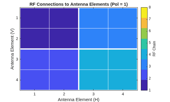
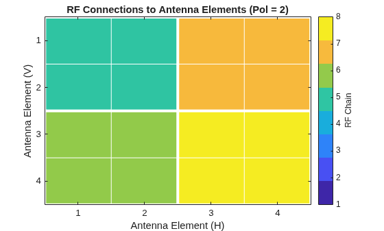
Plot how each RF chain connects to each subarray of the transmit antenna array. Each color represents an RF chain that connects to a subarray of antenna elements. The plot displays polarizations in separate figures.
plotRFConnectionsToSubarrays(rfc,simParameters.TransmitAntennaArray);
Obtain and display the overall number of antennas in each array.
simParameters.NTxAnts = numAntennaElements(simParameters.TransmitAntennaArray);
simParameters.NRxAnts = numAntennaElements(simParameters.ReceiveAntennaArray);
disp("Number of transmit antennas: " + simParameters.NTxAnts);
Number of transmit antennas: 32
disp("Number of receive antennas: " + simParameters.NRxAnts);Number of receive antennas: 4
Propagation Channel Configuration
Configure the delay profile, delay spread, and maximum Doppler shift of the CDL propagation channel for the simulation. You can configure the antenna array geometry in the Antenna Array Configuration section. The selected parameters represent a typical FR2 scenario:
Short delay spread (TR 38.901 Table 7.7.3-2 reports ~20–60 ns for InH and UMi at FR2).
Doppler shift corresponding to slow-moving user equipment (UE) at 28 GHz (; where km/h gives ~78 Hz).
simParameters.DelayProfile = "CDL-C";   % "CDL-A",...,"CDL-E"
simParameters.DelaySpread = 30e-9;      % s
simParameters.CarrierFrequency = 28e9;  % Hz (FR2 band)
simParameters.MaximumDopplerShift = 78; % Hz (~3 km/h at 28 GHz)
simParameters.ChannelSeed = 73;         % CDL random-stream seed. For reproducibility.

simParameters.Channel = createChannel(simParameters);

simParameters = validateParameters(simParameters);
Digital Precoder and Analog Beamformer
In a 5G NR system, the gNB uses CSI from the UE or uplink channel estimates to select suitable digital precoders and analog beamformers. For UE-reported CSI feedback, the gNB can beamform multiple CSI-RS processes independently with a predefined codebook of analog beamformers. Then, the gNB can use the CSI feedback to select appropriate analog beamformers in later data transmissions. For more information on CSI-based and reciprocity-based digital precoding, see the NR PDSCH Throughput Using Channel State Information Feedback and TDD Reciprocity-Based PDSCH MU-MIMO Using SRS examples.
The example computes the two stages in this processing order. The analog beamformer applies per-RF-chain phase-shifter weights in the time domain after the RF chains. The digital precoder operates in the frequency domain on the Nrfc RF-chain ports before OFDM modulation.
simParameters.AnalogCodebook.Azimuth = linspace(-60,60,16); % deg, 16 azimuths spanning [-60,60]
simParameters.AnalogCodebook.DownTilt = [0 5 10];           % deg, downtilt candidates
Analog Beamformer Codebook Selection
Build a codebook of candidate analog beams covering the desired angular sector. The codebook uses constant-modulus steering vectors at uniformly spaced azimuth and elevation angles. The example sweeps one N-port CSI-RS resource per codebook direction and selects the strongest beam by L1-RSRP. Because each resource carries one beam, the strongest CRI identifies one codebook direction. The example steers every RF chain of in that direction, so all subarrays point coherently at the strongest beam.
[channel,maxChDelay] = setupChannel(simParameters);
[N0,noiseEst] = setupReceiver(simParameters,channel);
[F,analogCSIReport] = selectAnalogBeamFromCSI(simParameters,channel,N0);

disp("Azimuth of the selected CRI (deg):  " + mat2str(round(analogCSIReport.SelectedAzimuth,1)));
Azimuth of the selected CRI (deg): 20
disp("Downtilt of the selected CRI (deg): " + mat2str(round(analogCSIReport.SelectedDownTilt,1)));Downtilt of the selected CRI (deg): 0
Display the radiation pattern associated with the selected beam. Because the analog stage steers every RF chain in the same direction, all subarrays share this pattern.
plotBeams(simParameters.TransmitAntennaArray.SubarraySize, ...
    simParameters.TransmitAntennaArray.ElementSpacing,F,1);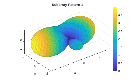
CSI-Driven Digital Precoder
The digital stage uses a CSI-driven Type-I single-panel PMI selection on the effective channel — that is, on the MIMO channel after the analog beamformer . The selectDigitalPrecoderFromCSI function computes the precoder from a single multi-port CSI-RS.
[W,digitalCSIReport] = selectDigitalPrecoderFromCSI(simParameters,F,channel,N0,noiseEst);
disp("Reported PMI: i1 = " + mat2str(digitalCSIReport.ReportedPMI.i1) + ...
    ", i2 = " + mat2str(digitalCSIReport.ReportedPMI.i2));
Reported PMI: i1 = [1 1 1], i2 = 2
disp("Reported RI: " + mat2str(digitalCSIReport.ReportedRI));Reported RI: 2
Transmit and Receive PDSCH with Hybrid Beamforming
Apply the digital precoder and analog beamformer to a PDSCH transmission, pass the CP-OFDM waveform through the CDL channel, and recover the transmitted data.
% Extract carrier and PDSCH configuration parameters
carrier = simParameters.Carrier;
pdsch = simParameters.PDSCH;

% Create an OFDM resource grid for a slot
dlGrid = nrResourceGrid(carrier,Nrfc);

% Use the CSI report to set the number of layers and
% modulation of the PDSCH
pdsch.Modulation = digitalCSIReport.Modulation;
pdsch.NumLayers = digitalCSIReport.ReportedRI;

% Calculate the RE capacity for PDSCH allocation
[pdschIndices,pdschIndicesInfo] = nrPDSCHIndices(carrier,pdsch);

% Create DL-SCH encoder and decoder system objects to perform transport
% channel encoding and decoding
encodeDLSCH = nrDLSCH;
decodeDLSCH = nrDLSCHDecoder;

% Transport block generation
trBlkSizes = nrTBS(pdsch,digitalCSIReport.TargetCodeRate);
for cwIdx = 1:pdsch.NumCodewords
    % New data for current codeword then create a new DL-SCH transport block
    trBlk = randi([0 1],trBlkSizes(cwIdx),1);
    setTransportBlock(encodeDLSCH,trBlk,cwIdx-1);
end

% Encode the DL-SCH transport blocks
RV = zeros(1,pdsch.NumCodewords);
codedTrBlocks = encodeDLSCH(pdsch.Modulation,pdsch.NumLayers, ...
    pdschIndicesInfo.G,RV);

% PDSCH modulation, digital precoding and mapping
pdschSymbols = nrPDSCH(carrier,pdsch,codedTrBlocks);
[pdschAntSymbols,pdschAntIndices] = nrPDSCHPrecode(carrier,pdschSymbols,pdschIndices,W);
dlGrid(pdschAntIndices) = pdschAntSymbols;

% PDSCH DM-RS digital precoding and mapping
dmrsSymbols = nrPDSCHDMRS(carrier,pdsch);
dmrsIndices = nrPDSCHDMRSIndices(carrier,pdsch);
[dmrsAntSymbols,dmrsAntIndices] = nrPDSCHPrecode(carrier,dmrsSymbols,dmrsIndices,W);
dlGrid(dmrsAntIndices) = dmrsAntSymbols;

% OFDM modulation
txWaveform = nrOFDMModulate(carrier,dlGrid);

% Analog beamforming of time-domain transmit waveform
txWaveform = analogBeamformWaveform(txWaveform,F,rfc,simParameters.NTxAnts);

% Pass waveform through propagation channel
txWaveform = [txWaveform; zeros(maxChDelay,size(txWaveform,2))];
[rxWaveform,ofdmResponse,timingOffset] = channel(txWaveform,carrier);

% Add AWGN to the received time-domain waveform
noise = N0*randn(size(rxWaveform),like=1i);
rxWaveform = rxWaveform + noise;

% Synchronize the received waveform
rxWaveform = rxWaveform(1+timingOffset:end,:);

% OFDM demodulate the received waveform
rxGrid = nrOFDMDemodulate(carrier,rxWaveform);

if simParameters.PerfectChannelEstimator
    % Combine perfect channel estimate to account for analog beamformers
    Hest = combineChannelEstimate(ofdmResponse,F,rfc,simParameters.NTxAnts);

    % Get PDSCH resource elements from the received grid and channel
    % estimate
    [pdschRx,pdschHest,~,pdschHestIndices] = nrExtractResources(pdschIndices,rxGrid,Hest);

    % Apply digital precoding to channel estimate
    pdschHest = nrPDSCHPrecode(carrier,pdschHest,pdschHestIndices,W.');
else
    % Practical channel estimation between the received grid and
    % each transmission layer, using the PDSCH DM-RS for each
    % layer. This channel estimate includes the effect of
    % digital precoding and analog beamforming
    [Hest,noiseEst] = nrChannelEstimate(carrier,rxGrid,dmrsIndices,dmrsSymbols,CDMLengths=pdsch.DMRS.CDMLengths);

    % Get PDSCH resource elements from the received grid and channel
    % estimate
    [pdschRx,pdschHest] = nrExtractResources(pdschIndices,rxGrid,Hest);
end

% Equalize received PDSCH symbols
[pdschEq,eqCSIScaling] = nrEqualizeMMSE(pdschRx,pdschHest,noiseEst);

% Decode PDSCH physical channel
[dlschLLRs,rxSymbols] = nrPDSCHDecode(carrier,pdsch,pdschEq,noiseEst);

% Scale LLRs
eqCSIScaling = nrLayerDemap(eqCSIScaling); % CSI scaling layer demapping
for cwIdx = 1:pdsch.NumCodewords
    Qm = length(dlschLLRs{cwIdx})/length(rxSymbols{cwIdx});        % bits per symbol
    eqCSIScaling{cwIdx} = repmat(eqCSIScaling{cwIdx}.',Qm,1);      % expand by each bit per symbol
    dlschLLRs{cwIdx} = dlschLLRs{cwIdx} .* eqCSIScaling{cwIdx}(:); % scale LLRs
end

% Decode the DL-SCH transport channel
decodeDLSCH.TransportBlockLength = trBlkSizes;
decodeDLSCH.TargetCodeRate = digitalCSIReport.TargetCodeRate;
[decbits,blkerr] = decodeDLSCH(dlschLLRs,pdsch.Modulation,pdsch.NumLayers,RV);
Results
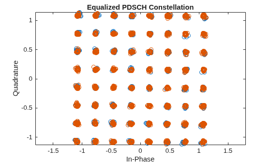
Display the in-phase and quadrature constellation of the received PDSCH symbols and measure their error vector magnitude (EVM). To check for transmission errors, inspect the transport block CRC result reported by the DL-SCH decoder.
figure;
plot(pdschEq,"o");
xlabel("In-Phase");
ylabel("Quadrature");
axis equal;
title("Equalized PDSCH Constellation");
measureEVM = comm.EVM;
EVM = measureEVM(pdschSymbols,pdschEq);
disp("Average PDSCH EVM: " + mean(EVM) + "%.");
Average PDSCH EVM: 1.1335%.
if any(blkerr)
    disp("Transmission error: transport block CRC failed.");
else
    disp("Transmission successful: transport block CRC passed.");
end
Transmission successful: transport block CRC passed.
References
[1] 3GPP TS 38.211, "NR; Physical channels and modulation." 3rd Generation Partnership Project; Technical Specification Group Radio Access Network.
[2] 3GPP TS 38.214, "NR; Physical layer procedures for data." 3rd Generation Partnership Project; Technical Specification Group Radio Access Network.
[3] 3GPP TS 38.215, "NR; Physical layer measurements." 3rd Generation Partnership Project; Technical Specification Group Radio Access Network.
[4] 3GPP TR 38.901, "Study on channel model for frequencies from 0.5 to 100 GHz." 3rd Generation Partnership Project; Technical Specification Group Radio Access Network.
Local Functions
function [F,analogReport] = selectAnalogBeamFromCSI(simParameters,channel,N0)
%selectAnalogBeamFromCSI Analog beam selection by L1-RSRP over a CSI-RS sweep
%   [F,ANALOGREPORT] = selectAnalogBeamFromCSI(SIMPARAMETERS,CHANNEL,N0)
%   sweeps one aperiodic NZP-CSI-RS resource per candidate direction of a
%   constant-modulus steering-vector codebook, measures L1-RSRP per
%   direction as defined in TS 38.215 Section 5.1.2, and returns the analog
%   beamforming weights F together with the report ANALOGREPORT of the
%   strongest CRI.
%
%   SIMPARAMETERS is a scalar structure with the following fields:
%      Carrier              - nrCarrierConfig object
%      NTxAnts              - Total number of transmit antennas
%      TransmitAntennaArray - Structure with SubarraySize, ElementSpacing,
%                             NumRFChains, and RFChainConnections
%      NumCSIRSPorts        - Number of CSI-RS antenna ports per resource
%                             (P_csirs). Equal to NumRFChains here so every
%                             port of a swept resource drives one subarray.
%      AnalogCodebook       - Structure with Azimuth and DownTilt vectors
%                             (in degrees)
%
%   CHANNEL is an nrCDLChannel object.
%
%   N0 is the AWGN noise standard deviation applied to the time-domain
%   waveform.
%
%   F is a complex column vector of size [Nelem*Nrfc x 1] with column-major
%   per-RF-chain stacking, where reshape(F,Nelem,Nrfc) gives the analog
%   weight matrix whose k-th column drives the k-th RF chain and
%   Nelem = prod(SubarraySize).
%
%   ANALOGREPORT is a structure with the following fields:
%      SelectedCRI      - CSI-RS resource indicator of the strongest resource
%      SelectedAzimuth  - Azimuth of the selected CRI (deg)
%      SelectedDownTilt - Downtilt of the selected CRI (deg)
%      RSRP             - RSRP per candidate CRI (numBeams x 1)
%      CodebookF        - Full codebook (Nelem x numBeams). Callers can
%                         assemble a custom F by picking any subset of
%                         columns and stacking with
%                         reshape(CodebookF(:,subset),[],1)
%      NumRFChains      - Number of RF chains

    % Extract local variables
    subarraySize = simParameters.TransmitAntennaArray.SubarraySize;
    elementSpacing = simParameters.TransmitAntennaArray.ElementSpacing;
    Nrfc = simParameters.TransmitAntennaArray.NumRFChains;
    rfc = simParameters.TransmitAntennaArray.RFChainConnections;
    Pcsirs = simParameters.NumCSIRSPorts;
    codebookAzimuth = simParameters.AnalogCodebook.Azimuth;
    codebookDownTilt = simParameters.AnalogCodebook.DownTilt;
    carrier = simParameters.Carrier;
    NTxAnts = simParameters.NTxAnts;

    % Build the codebook (constant-modulus steering vectors)
    [Az,Tl] = ndgrid(codebookAzimuth,codebookDownTilt);
    azList = Az(:);
    tlList = Tl(:);
    numBeams = numel(azList);

    Nelem = prod(subarraySize);
    codebook = zeros(Nelem,numBeams);
    for c = 1:numBeams
        codebook(:,c) = analogBeamformer(subarraySize,elementSpacing,1,azList(c),tlList(c));
    end

    % Build one Pcsirs-port aperiodic NZP-CSI-RS configuration object, then
    % populate the CSI-RS resource grid once. The grid depends only on
    % carrier and csirs (both loop-invariant), so the same rfGrid drives
    % every sweep slot; only the analog weights Fs change per iteration.
    csirs = buildNportCSIRS(simParameters);
    rfGrid = nrResourceGrid(carrier,Pcsirs);
    csirsInd = nrCSIRSIndices(carrier,csirs);
    csirsSym = nrCSIRS(carrier,csirs);
    rfGrid(csirsInd) = csirsSym;

    % Broadcast each column of the codebook to every RF chain: same direction on
    % all N subarrays, driven coherently.
    Fs = repmat(codebook,Nrfc,1); % [Nelem*Nrfc x numBeams]

    % Compute the L1-RSRP for each beam direction
    rsrpLin = zeros(numBeams,1);
    for s = 1:numBeams
        rxGrid = processCSIRSLink(carrier,rfGrid,Fs(:,s),rfc,NTxAnts,channel,N0);

        % One resource in the config -> RSRPPerAntenna is NRxAnts x 1 (dBm).
        % Sum linear power across Rx antennas for the direction-level RSRP.
        meas = nrCSIRSMeasurements(carrier,csirs,rxGrid);
        rsrpLin(s) = sum(10.^(meas.RSRPPerAntenna/10),"all");
    end

    % Select the strongest beam and use it for every RF chain
    [~,bestIdx] = max(rsrpLin);

    % Extract the output F matrix
    F = Fs(:,bestIdx);

    % Construct the analog report
    analogReport = struct();
    analogReport.SelectedCRI = bestIdx;
    analogReport.SelectedAzimuth = azList(bestIdx);
    analogReport.SelectedDownTilt = tlList(bestIdx);
    analogReport.RSRP = 10*log10(rsrpLin + eps);
    analogReport.CodebookF = codebook;
    analogReport.NumRFChains = Nrfc;
end

function csirs = buildNportCSIRS(simParameters)
%buildNportCSIRS Aperiodic NZP-CSI-RS resource with N ports
%   CSIRS = buildNportCSIRS(SIMPARAMETERS) returns an nrCSIRSConfig object
%   configured as a single N-port aperiodic NZP-CSI-RS resource, with the
%   RowNumber and SubcarrierLocations dictated by TS 38.211
%   Table 7.4.1.5.3-1.
%
%   SIMPARAMETERS is a scalar structure with the following fields:
%      Carrier              - nrCarrierConfig object
%      PDSCH                - nrPDSCHConfig object
%      NumCSIRSPorts        - Number of CSI-RS antenna ports per resource
%                             (P_csirs). Equal to NumRFChains here so every
%                             port of a swept resource drives one subarray.

    [rowNumber, subcarriers, symbols, density] = csirsAllocationParameters(simParameters);

    csirs = nrCSIRSConfig;
    csirs.CSIRSType = "nzp";
    csirs.RowNumber = rowNumber;
    csirs.Density = density;
    csirs.NumRB = simParameters.Carrier.NSizeGrid;
    csirs.RBOffset = 0;
    csirs.CSIRSPeriod = "on";
    csirs.SubcarrierLocations = subcarriers;
    csirs.SymbolLocations = symbols;

end

function [rowNumber, subcarriers, symbols, density] = csirsAllocationParameters(simParameters)
    % Select CSI-RS row number, subcarrier and symbol locations that are
    % suitable for the input carrier, PDSCH, and transmit antenna array
    % specified in simParameters. See TS 38.211 Table 7.4.1.5.3-1 and TS 38.214
    % Table 5.2.2.2.1-2.

    carrier = simParameters.Carrier;
    pdsch = simParameters.PDSCH;

    % Select row number from number of ports
    numPorts   = [1 2 4 8 12 16 24 32];
    rowNumbers = [2 3 4 6  9 11 13 16];
    if isfield(simParameters,"NumCSIRSPorts")
        userNumPorts = simParameters.NumCSIRSPorts;
    else
        userNumPorts = numAntennaElements(simParameters.TransmitAntennaArray);
    end
    rowNumber = rowNumbers(userNumPorts==numPorts);
    if isempty(rowNumber)
        error("csirsAllocationParameters:UnsupportedNumCSIRSPorts", ...
            "No row of TS 38.211 Table 7.4.1.5.3-1 is wired up for " + userNumPorts + ...
            " CSI-RS ports. Set the port count to one of the values allowed " + ...
            "by the table: {" + strjoin(string(numPorts),", ") + "}.");
    end

    % CSI-RS subcarriers
    kiLengths = [1 1 1 1 1 4 2 2 6 3 4 4 3 3 3 4 4 4]; % Number of subcarriers for each row
    numSubcarriers = kiLengths(rowNumber);
    scStep = 12./numSubcarriers;
    subcarriers = 0:scStep:11; %#ok<BDSCI>

    % CSI-RS OFDM symbols
    dmrsind = nrPDSCHDMRSIndices(carrier,pdsch,"IndexStyle","subscript");
    dmrssym = unique(dmrsind(:,2))-1; % 0-based indices
    slotSymbolSet = 2:carrier.SymbolsPerSlot-2;
    slotSymbolSet = setdiff(slotSymbolSet,dmrssym);
    nsyms = [1 1 1 1 1 1 1 1 1 1 1 1 2 2 1 2 2 1]; % Number of symbols for each row
    nsym = nsyms(rowNumber);
    symbols = slotSymbolSet(1:2:2*nsym);

    if ~isfield(simParameters,"CSIRS")
        density = "one";
    else
        density = simParameters.CSIRS.Density;
        if (density ~= "one" ) && any(rowNumber == (4:10))
            density = "one";
            warning("csirsAllocationParameters:UnsupportedDensity", ...
            "For the transmit array panel dimensions, the CSI-RS density must be 'one'. The density is set to 'one'.");
        end
    end

end

function rxGrid = processCSIRSLink(carrier,rfGrid,F,rfc,NTxAnts,channel,N0)
%processCSIRSLink Transmit and receive a CSI-RS waveform through the channel.
%   Applies analog beamforming, propagation, AWGN, and OFDM demodulation.
%   Assumes perfect synchronization by removing the channel delay before
%   demodulation.

    maxChDelay = info(channel).MaximumChannelDelay;
    txWaveform = nrOFDMModulate(carrier,rfGrid);
    txWaveform = analogBeamformWaveform(txWaveform,F,rfc,NTxAnts);
    txWaveform = [txWaveform; zeros(maxChDelay,size(txWaveform,2))];

    [rxWaveform,~,timingOffset] = channel(txWaveform,carrier);
    noise = N0*randn(size(rxWaveform),like=1i);
    rxWaveform = rxWaveform + noise;
    rxWaveform = rxWaveform(1+timingOffset:end,:);
    rxGrid = nrOFDMDemodulate(carrier,rxWaveform);
end

function [W,digitalReport] = selectDigitalPrecoderFromCSI(simParameters,F,channel,N0,noiseEst)
%selectDigitalPrecoderFromCSI Digital precoder selection from a Type-I PMI report
%   [W,DIGITALREPORT] = selectDigitalPrecoderFromCSI(SIMPARAMETERS,F,CHANNEL,N0,NOISEEST)
%   pre-beamforms a Pcsirs-port aperiodic NZP-CSI-RS resource through the
%   analog weights F, drives it through the CDL channel, and derives a
%   digital precoder W from a Type-I PMI report as defined in TS 38.214
%   Section 5.2.2.2. selectDigitalPrecoderFromCSI also returns the report
%   DIGITALREPORT.
%
%   SIMPARAMETERS is a scalar structure with the following fields:
%      Carrier              - nrCarrierConfig object
%      NTxAnts              - Total number of transmit antennas
%      PDSCH                - nrPDSCHConfig object
%      TransmitAntennaArray - Structure with NumRFChains and
%                             RFChainConnections
%      NumCSIRSPorts        - Number of CSI-RS antenna ports per resource
%                             (P_csirs). Selects the RowNumber and panel
%                             dimensions used to build the report
%      PanelDimensions      - [Ng N1 N2] triple passed straight
%                             to nrCSIReportConfig
%
%   F is a complex column vector of analog beamforming weights with size
%   [Nelem*Nrfc x 1], where Nelem is the number of antenna elements per
%   subarray and Nrfc is the number of RF chains. This is the same shape
%   returned by selectAnalogBeamFromCSI.
%
%   CHANNEL is an nrCDLChannel object.
%
%   N0 is the AWGN noise standard deviation applied to the time-domain
%   waveform.
%
%   NOISEEST is the frequency-domain noise variance.
%
%   W is the digital precoder, a complex matrix of size [NumLayers x Nrfc]
%   (rows are layers, columns are RF chains), scaled to unit power per RF
%   chain (||W||_F^2 = Nrfc).
%
%   DIGITALREPORT is a structure with the following fields:
%      ReportedPMI    - Structure or vector reported by nrCSIReportCSIRS
%      ReportedRI     - Reported rank indicator (scalar)
%      ReportedCQI    - Reported channel quality indicator (scalar or vector)
%      Modulation     - Modulation selected via the CQI table
%      TargetCodeRate - Target code rate selected via the CQI table

    carrier = simParameters.Carrier;
    Nrfc = simParameters.TransmitAntennaArray.NumRFChains;
    Pcsirs = simParameters.NumCSIRSPorts;
    NTxAnts = simParameters.NTxAnts;
    rfc = simParameters.TransmitAntennaArray.RFChainConnections;

    % Build one Pcsirs-port aperiodic NZP-CSI-RS configuration object, then
    % populate the CSI-RS resource grid.
    csirs = buildNportCSIRS(simParameters);
    rfGrid = nrResourceGrid(carrier,Pcsirs);
    csirsInd = nrCSIRSIndices(carrier,csirs);
    csirsSym = nrCSIRS(carrier,csirs);
    rfGrid(csirsInd) = csirsSym;

    rxGrid = processCSIRSLink(carrier,rfGrid,F,rfc,NTxAnts,channel,N0);

    % UE-side channel estimate against the CSI-RS, returning Hest of size
    % [K x Nsym x NRxAnts x Pcsirs]
    [Hest,~] = nrChannelEstimate(carrier,rxGrid,csirsInd,csirsSym,CDMLengths=csirsCDMLengths(csirs));

    % Type-I single-panel PMI/RI/CQI report
    reportConfig = nrCSIReportConfig;
    reportConfig.NSizeBWP = carrier.NSizeGrid;
    reportConfig.NStartBWP = 0;
    reportConfig.CodebookType = "type1SinglePanel";
    reportConfig.PanelDimensions = simParameters.PanelDimensions;
    reportConfig.PMIFormatIndicator = "wideband";
    reportConfig.CQIFormatIndicator = "wideband";
    [csiReport,csiInfo] = nrCSIReportCSIRS(carrier,csirs,reportConfig,simParameters.PDSCH.DMRS,Hest,noiseEst);

    % Map CSI to modulation and target code rate
    [modulation,tcr] = CSI2MCS(reportConfig.CQITable,csiReport);

    % Reconstruct W from the reported precoding matrix.
    % csiInfo.PrecodingMatrix is [Pcsirs x numLayers x numSubbands]. This
    % example couples Pcsirs == Nrfc so the Pcsirs dimension matches the
    % per-RF-chain dimension expected by nrPDSCHPrecode.
    Wreported = csiInfo.PrecodingMatrix(:,:,1);
    % PrecodingMatrix has unit total power (TS 38.214 5.2.2.2). Scale to
    % unit power per RF chain (||W||_F^2 = Nrfc): with unit-modulus F this
    % runs every antenna element at unit power, matching the CSI-RS pilots
    % and fixing total transmit power at NTxAnts regardless of the subarray
    % partition.
    W = sqrt(Nrfc) * Wreported.';

    % Construct the digital report
    digitalReport = struct();
    digitalReport.ReportedPMI = csiReport.PMISet;
    digitalReport.ReportedRI = csiReport.RI;
    digitalReport.ReportedCQI = csiReport.CQI;
    digitalReport.Modulation = modulation;
    digitalReport.TargetCodeRate = tcr;
end

% Map CQI to PDSCH MCS for the specified CQI table
function [modulation,tcr] = CSI2MCS(tableInput,csiReport)

    % Configure MCS based on CQI
    cqi = csiReport.CQI(1,:); % Wideband CQI
    ncw = ceil(csiReport.RI/4);
    cqi = max([ones(1,ncw); cqi],[],1); % map CQI 0 -> CQI 1

    persistent cqiTable tableName;
    if (isempty(cqiTable)||~strcmpi(tableName,tableInput))
        tableName = tableInput;
        cqiTableClass = nrCQITables;
        classProp = properties(cqiTableClass);
        cqiTable = cqiTableClass.(classProp{contains(classProp,tableInput,IgnoreCase=true)});
    end
    % add 1 to index as it starts from 0
    modulation = cqiTable.Modulation(cqi+1);
    % remove modulation if it is "Out of range"
    modulation = modulation(~strcmpi(modulation,"Out of Range"));
    tcr = cqiTable.TargetCodeRate(cqi+1);
end

function cdm = csirsCDMLengths(csirs)
    %csirsCDMLengths [FD TD] CDM lengths implied by the CDMType of CSIRS.
    %   Used to pass the correct CDMLengths to nrChannelEstimate for CSI-RS
    %   estimation.

    cdmType = csirs.CDMType;
    if iscell(cdmType)
        % All reference symbols passed to nrChannelEstimate must use one
        % consistent CDM arrangement
        cdmType = cdmType{1};
    end
    switch lower(string(cdmType))
        case "nocdm",   cdm = [1 1];
        case "fd-cdm2", cdm = [2 1];
        case "cdm4",    cdm = [2 2];
        case "cdm8",    cdm = [2 4];
        otherwise
            error("csirsCDMLengths:UnsupportedCDMType", ...
                "Unsupported CSI-RS CDMType: " + cdmType);
    end
end

function F = analogBeamformer(subarraySize,elementSpacing,numRFChains,azimuth,downTilt)
% Define analog beamformers with directions defined by the set of azimuth
% and downtilt input angles.

    % Expand azimuth and elevation as required
    azimuth= azimuth(:);
    downTilt = downTilt(:);
    if isscalar(azimuth)
        azimuth = repmat(azimuth,numel(downTilt),1);
    end
    if isscalar(downTilt)
        downTilt = repmat(downTilt,numel(azimuth),1);
    end

    % Arrange azimuth and downtilt values in the third dimension of the
    % array for convenience
    azimuth = permute(azimuth,[3 2 1]);
    downTilt = permute(downTilt,[3 2 1]);

    % Spherical to Cartesian coordinates factors
    az = azimuth*pi/180;
    el = -downTilt*pi/180;
    r = 1;
    [~,ys,zs] = sph2cart(az,el,r);

    % Vertical steering vector
    Nz = subarraySize(1);
    dz = elementSpacing(1);
    vsv = exp(-1i*2*pi*dz*((0:Nz-1)-(Nz-1)/2).'.*zs);

    % Horizontal steering vector
    Ny = subarraySize(2);
    dy = elementSpacing(2);
    hsv = exp(-1i*2*pi*dy*((0:Ny-1)-(Ny-1)/2).*ys);

    % Subarray steering vector
    F = reshape(pagemtimes(vsv,hsv),[],1);

    % Replicate beamformers to match the number of RF chains
    s = min(numel(azimuth),numRFChains);
    F = repmat(F,ceil(numRFChains/s),1);
    F = F(1:numRFChains*Nz*Ny);
end

function RFConnections = RFChainConnections(antArray)
% Define the connections between RF chains and antenna array elements

    % Antenna array dimensions
    M = antArray.Size(1);
    N = antArray.Size(2);
    Mas = antArray.SubarraySize(1);
    Nas = antArray.SubarraySize(2);
    Msa = M/Mas;
    Nsa = N/Nas;
    P = antArray.NumPolarizations;

    if mod(Msa,1) || mod(Nsa,1)
        error("RFChainConnections:NonIntegerSubarrayCount", "Array and subarray sizes must be such that the array can be partitioned into an integer number of equal-size subarrays.");
    end

    % Determine the antenna element indices connected to each RF chain
    RFConnections = zeros(M,N,P);
    numSubarrays = Msa*Nsa;
    for p = 1:P
        RFConnections(:,:,p) = kron(reshape(1:numSubarrays,Msa,Nsa),ones(Mas,Nas)) + numSubarrays*(p-1);
    end

    % Check that there are no repetitions
    numAntElem = M*N*P;
    for a = 0:numAntElem-1
        rfca = RFConnections(a + (1:numAntElem:end));
        rfca(rfca==0) = NaN;
        if numel(rfca) ~= numel(unique(rfca))
            error("RFChainConnections:DuplicateAntennaConnection", "The same RF chain has been connected to the same antenna multiple times.");
        end
    end
end

function outWaveform = analogBeamformWaveform(waveform,F,RFConnections,NumAntElements)
% Apply beamforming weights F to input waveform. The beamforming weights F
% must be sorted following the RF chain connection list RFConnections.

    % Reshape RF connections to 2-D (NumAntElements-by-NRF) if needed. NRF is
    % the number of RF chains connected to an antenna element. For more
    % information, see the RF Connections to Antenna Elements section.
    if ~(height(RFConnections) == NumAntElements) || ~ismatrix(RFConnections)
        RFConnections = reshape(RFConnections,NumAntElements,[]);
    end

    % Preallocate output waveform (NTimeSamples-by-NumAntElements)
    NTimeSamples = size(waveform,1);
    outWaveform = zeros(NTimeSamples,NumAntElements);

    % Apply beamforming weights to input waveform
    NRF = size(waveform,2);
    for rf = 1:NRF
        rfAntennaElement = RFConnections == rf;
        antennaElement = any(rfAntennaElement,2);
        outWaveform(:,antennaElement) = outWaveform(:,antennaElement) + waveform(:,rf).*F(rfAntennaElement).' ;
    end

end

function estChannelGrid = combineChannelEstimate(estChannelGrid,F,RFConnections,NumAntElements)
% Combine input perfect channel estimates with input analog beamforming
% weights F. The beamforming weights F must be sorted following the RF
% chain connections RFConnections. The input perfect channel estimate array
% of size [K-by-N-by-Nr-by-Nt] contains estimates for each transmit antenna
% element. The output array of size [K-by-N-by-Nr-by-NRF] contains perfect
% channel estimates for each RF chain.

    % Reshape RF connection list to 2-D (NumAntennaElements-by-N) if needed
    if ~(height(RFConnections) == NumAntElements) || ~ismatrix(RFConnections)
        RFConnections = reshape(RFConnections,NumAntElements,[]);
    end

    NRF = numunique(RFConnections);

    % Change estimate dimension order for convenience before combining
    H = permute(estChannelGrid,[3 4 1 2]);

    % Combine estimates using beamforming weights
    Hbf = zeros([size(H,1),NRF,size(H,[3,4])]);
    for rf = 1:NRF
        rfAntennaElement = RFConnections == rf;
        antennaElement = any(rfAntennaElement,2);
        Hbf(:,rf,:,:) = pagemtimes(H(:,antennaElement,:,:),F(rfAntennaElement));
    end

    % Change estimate dimension order back
    estChannelGrid = permute(Hbf,[3 4 1 2]);
end

function channel = createChannel(simParameters)
% Create and configure the propagation channel

    if contains(simParameters.DelayProfile,"CDL")

        % Create CDL channel
        channel = nrCDLChannel;

        % Tx antenna array configuration in CDL channel. The size of the
        % antenna array is [M,N,P,Mg,Ng]. M and N are the number of rows
        % and columns in the antenna array, respectively. P is the number
        % of polarizations (1 or 2). Mg and Ng are the number of row and
        % column array panels, respectively.
        txArray = simParameters.TransmitAntennaArray;

        channel.TransmitAntennaArray.Size = [txArray.Size txArray.NumPolarizations 1 1];
        channel.TransmitAntennaArray.ElementSpacing = [txArray.ElementSpacing 1 1]; % Element spacing in wavelengths
        channel.TransmitAntennaArray.PolarizationAngles = [-45 45];                 % Polarization angles in degrees

        % Rx antenna array configuration in CDL channel
        rxArray = simParameters.ReceiveAntennaArray;

        channel.ReceiveAntennaArray.Size = [rxArray.Size rxArray.NumPolarizations 1 1];
        channel.ReceiveAntennaArray.ElementSpacing = [rxArray.ElementSpacing 1 1];  % Element spacing in wavelengths
        channel.ReceiveAntennaArray.PolarizationAngles = [0 90];                    % Polarization angles in degrees

    else
        error("createChannel:UnsupportedChannel","Channel (" + simParameters.DelayProfile + ...
            ") not supported. Only CDL channel is supported.");
    end

    % Configure other channel parameters: delay profile, delay spread,
    % maximum Doppler shift, carrier center frequency, and random-stream
    % seed.
    channel.DelayProfile = simParameters.DelayProfile;
    channel.DelaySpread = simParameters.DelaySpread;
    channel.MaximumDopplerShift = simParameters.MaximumDopplerShift;
    channel.CarrierFrequency = simParameters.CarrierFrequency;
    channel.Seed = simParameters.ChannelSeed;

    % Get information about the baseband waveform after OFDM modulation step
    waveInfo = nrOFDMInfo(simParameters.Carrier);

    % Update channel sample rate based on carrier information
    channel.SampleRate = waveInfo.SampleRate;

    % Specify the channel response output to obtain the OFDM response of
    % the channel
    channel.ChannelResponseOutput = "ofdm-response";

end

function [channel,maxChannelDelay] = setupChannel(simParameters)
% Reset the propagation channel and obtain the maximum channel delay
%
% The same channel object is threaded through every CSI stage and the PDSCH
% slot - its internal sample clock is the only mechanism that enforces
% Doppler evolution across stages. Do not rebuild or re-reset the channel
% between stages; that silently restarts the fading realization from
% t=channel.InitialTime and breaks the inter-stage timeline.

    % Extract channel
    channel = simParameters.Channel;
    channel.reset();

    % Get the channel information
    chInfo = info(channel);
    maxChannelDelay = chInfo.MaximumChannelDelay;

end

function [N0, noiseEst] = setupReceiver(simParameters,channel)
% Calculate noise standard deviation and noise variance

    % Calculate noise standard deviation. Normalize noise power by the FFT
    % size used in OFDM modulation, as the OFDM modulator applies this
    % normalization to the transmitted waveform.
    SNRdB = simParameters.SNRIn;
    SNR = 10^(SNRdB/10);
    waveInfo = nrOFDMInfo(simParameters.Carrier);
    N0 = 1/sqrt(double(waveInfo.Nfft)*SNR);

    % Also normalize by the number of receive antennas if the channel
    % applies this normalization to the output
    if channel.NormalizeChannelOutputs
        chInfo = info(channel);
        N0 = N0/sqrt(chInfo.NumReceiveAntennas);
    end

    noiseEst = N0^2*double(waveInfo.Nfft);
end

function numElements = numAntennaElements(antArray)
% Calculate number of antenna elements in an antenna array

    numElements = antArray.NumPolarizations*prod(antArray.Size);

end

function simParameters = validateParameters(simParameters)
% Validate the simulation parameters

    % Validate number of layers, relative to the antenna geometry
    numlayers = simParameters.PDSCH.NumLayers;
    numRFChains = simParameters.TransmitAntennaArray.NumRFChains;
    nrxants = simParameters.NRxAnts;
    antennaDescription = "min(numRFChains,NRxAnts) = min(" + numRFChains + "," + nrxants + ") = " + min(numRFChains,nrxants);
    if numlayers > min(numRFChains,nrxants)
        error("ModelHybridBeamformingWithCDLChannelsExample:InvalidNumLayers", ...
            "The number of layers (" + numlayers + ") must satisfy NumLayers <= " + antennaDescription);
    end

    % Display a warning if the maximum possible rank of the channel equals
    % the number of layers
    if (numlayers > 2) && (numlayers == min(numRFChains,nrxants))
        warning("ModelHybridBeamformingWithCDLChannelsExample:ChannelRankEqualsNumLayers", ...
            "The maximum possible rank of the channel, given by " + antennaDescription + ...
            ", is equal to NumLayers (" + numlayers + ")." + ...
            " This can result in a decoding failure in certain channel conditions." + ...
            " Try decreasing the number of layers or increasing the channel rank" + ...
            " (use more transmit or receive antennas).");
    end

    % Validate the panel dimension for CSI reporting.
    % Panel dimensions are [Ng N1 N2] per nrCSIReportConfig. For
    % type1SinglePanel, Ng = 1 always; N1*N2 = Pcsirs/2 for dual-polarized
    % arrays (Pcsirs=1 is single-port and uses [1 1 1]). The code
    % auto-derives (N1,N2) from the array's subarray layout so the codebook
    % orientation matches the physical panel. If that pair is not one of
    % the (N1,N2) splits allowed by TS 38.214 Table 5.2.2.2.1-2 for this
    % Pcsirs, the code errors. Set simParameters.PanelDimensions to
    % override the auto-derivation and the error check.
    if ~isfield(simParameters,"PanelDimensions") || isempty(simParameters.PanelDimensions)
        array = simParameters.TransmitAntennaArray;
        N2derived = array.Size(1) / array.SubarraySize(1); % vertical
        N1derived = array.Size(2) / array.SubarraySize(2); % horizontal
        Pcsirs = simParameters.NumCSIRSPorts;
        if isTypeIPanelSplitAllowed(Pcsirs, N1derived, N2derived)
            simParameters.PanelDimensions = [1 N1derived N2derived];
        else
            error("ModelHybridBeamformingWithCDLChannelsExample:UnsupportedPanelLayout", ...
                "Subarray layout (%d horizontal x %d vertical) is not a " + ...
                "(N1,N2) split allowed for Pcsirs=%d per TS 38.214 Table 5.2.2.2.1-2.", ...
                N1derived, N2derived, Pcsirs);
        end
    end

end

function plotRFConnectionsToSubarrays(M,antArray)
% Plot RF connections to subarrays

    clims = [min(M(:)) max(M(:))];
    if clims(1) == clims(2)
        clims(2) = clims(1)+1;
    end

    nCols = size(M,2);
    nRows = size(M,1);
    Ws = antArray.SubarraySize(2);
    Hs = antArray.SubarraySize(1);
    numPol = size(M,3);

    for i = 1:numPol
        figure;
        imagesc(M(:,:,i),clims);

        % Plot lines separating elements and subarrays
        plotLines(nCols,nRows,Ws,Hs,3,"w");
        plotLines(nCols,nRows,1,1,0.5,"w");

        % Quantize colormap
        cm = colormap;
        colormap(cm(1:floor(size(cm,1)/(clims(2)-clims(1))-1):end,:)); % Adjust colormap to discrete values
        cb = colorbar;
        ylabel(cb,"RF Chain");

        % Add title and labels
        title("RF Connections to Antenna Elements (Pol = " + i + ")");
        xlabel("Antenna Element (H)");
        ylabel("Antenna Element (V)");
        xticks(1:nCols);
        yticks(1:nRows);
    end

end

function plotLines(W,H,Ws,Hs,lw,col)

    for row = 1:Hs:H+1
        line(0.5+[0,W],-0.5+[row,row],Color=col,LineWidth=lw);
    end
    for column = 1:Ws:W+1
        line([column,column]-0.5,0.5+[0,H],Color=col,LineWidth=lw);
    end

end

function plotBeams(subarrayDims,elementSpacing,F,rfIndex)

    if nargin == 3
        rfIndex = 1;
    end

    % Define 3-D plotting space in Cartesian coordinates
    ph = linspace(0,2*pi,100);
    th = linspace(-pi/2,pi/2,120);

    [TH,PH] = ndgrid(th,ph);
    [x,y,z] = sph2cart(PH,TH,1);
    r = [x(:) y(:) z(:)];

    % Calculate positions of each antenna element in a subarray
    nh = subarrayDims(2);
    dh = elementSpacing(2);
    hvec = dh*((0:nh-1)-(nh-1)/2);

    nv = subarrayDims(1);
    dv = elementSpacing(1);
    vvec = dv*((0:nv-1)-(nv-1)/2);

    [Dx,Dy] = meshgrid(hvec,vvec);
    d = [zeros(numel(Dx),1) Dx(:) Dy(:)];

    % Plot pattern using the input beam weights
    figure;
    for rf = 1:numel(rfIndex)
        thisF = F((rfIndex(rf)-1)*nh*nv + (1:nh*nv));
        A = reshape(sum(thisF.*exp(1i*2*pi*d*r'),1), size(x));
        [Ax,Ay,Az] = sph2cart(PH,TH,abs(A));
        nexttile;
        surf(Ax,Ay,Az,abs(A),EdgeAlpha=0.1);
        axis equal;
        title("Subarray Pattern " + rf);
        xlabel("x");
        ylabel("y");
    end
    colorbar;

end

function tf = isTypeIPanelSplitAllowed(Pcsirs,N1,N2)
    % Allowed (N1,N2) splits for type1SinglePanel per TS 38.214 Table
    % 5.2.2.2.1-2. Rows correspond to Pcsirs = 1, 2, 4, 8, 12, 16, 24, 32.
    persistent allowedPanelSplit
    if isempty(allowedPanelSplit)
        allowedPanelSplit = dictionary( ...
            [1 2 4 8 12 16 24 32], ...
            {[1 1],                             ...   % 1 port
            [1 1],                              ...   % 2 ports (Ng=1 by convention)
            [2 1],                              ...   % 4 ports
            [2 2; 4 1],                         ...   % 8 ports
            [3 2; 6 1],                         ...   % 12 ports
            [4 2; 8 1],                         ...   % 16 ports
            [4 3; 6 2; 12 1],                   ...   % 24 ports
            [4 4; 8 2; 16 1]});                       % 32 ports
    end
    if ~isKey(allowedPanelSplit,Pcsirs), tf = false; return; end
    tf = any(all(allowedPanelSplit{Pcsirs} == [N1 N2], 2));
end

