Streaming Sample Interface
What Is a Streaming Sample Interface?
In hardware, processing an entire frame of data at one time has a high cost in memory and area. To save resources, serial processing is preferable in HDL designs. Wireless HDL Toolbox™ blocks operate on one sample at a time rather than a frame. The blocks accept and return data as a serial stream of samples and control signals. The control signals indicate the frame boundaries. The protocol mimics the characteristics of a real-world system, including inactive intervals between samples and frames.
How Does a Streaming Sample Interface Work?
The control protocol uses start and end signals to demark each frame, and a valid signal to indicate which samples to process. The Wireless HDL Toolbox streaming sample protocol allows you to configure the number of idle cycles between samples and between frames. Idle cycles model the bursty character of real-world systems.
This protocol allows for frames of different sizes, such as if runt or partial frames enter the system due to synchronization changes.
Why Use a Streaming Sample Interface?
Format Independence
The blocks that use this interface do not need a configuration option for an exact frame size or inactive intervals. In addition, if you change the input data timing for your design, you do not need to update each block. Instead, update the stream configuration once at the serialization step. Some blocks still require a maximum frame size parameter to allocate memory resources.
Error Tolerance
By using a streaming sample interface with control signals, each Wireless HDL Toolbox block starts computation on a fresh set of samples at the start-of-frame signal. Computations on the new frame occur whether or not the block receives the end signal for the previous frame.
The protocol tolerates minor timing errors. If the number of valid and invalid cycles between start and end signals varies, the blocks continue to operate correctly. This protocol makes the system resilient to runt frames and synchronization changes.
The Wireless HDL Toolbox encoder blocks require minimum between-frame spacing to accommodate insertion of codewords. The turbo and convolutional decoder blocks require that the previous frame is decoded (has asserted the frame end signal) before the next frame arrives. The polar, LPDC, and RS encoder and decoder blocks provide a signal to indicate when the block is ready to receive the start of a new frame.
Sample Stream Conversion
Use the Frame To
Samples block to convert framed data to a stream of samples and control
signals that conform to this protocol. The control signals are grouped in a bus data
type called samplecontrol.
The Frame To
Samples block can serialize fixed-size frames. If your frames vary in size,
use the whdlFramesToSamples function to convert framed data to vectors of
samples and control signals in MATLAB®. Then import the vectors to Simulink®. Use the Sample Control Bus
Creator block to create a samplecontrol bus in your
model.
If your data is already in a serial format, design your own logic to generate these control signals from your existing serial control scheme.
Supported Sample Data Types
Wireless HDL Toolbox blocks have an input and output port, sample, for
the streaming sample data. The blocks capture one sample at a time from the input,
and produce one sample at a time for output. The samples can be one of these
supported data types.
| Port | Description | Data Type |
|---|---|---|
sample |
Scalar integer value that represents one sample. The protocol also allows for a vector of integer values that represent a single sample, such as for turbo-encoded samples. |
Supported data types include:
|
Streaming Sample Control Signals
Wireless HDL Toolbox blocks have an input and output port, ctrl, for the
frame control signals relating to each sample. These three control signals indicate
the validity of a sample and the boundaries of the frame. The control signal port is
a nonvirtual bus data type called samplecontrol. For details of
the bus data type, see Sample Control Bus.
Timing Diagram of Serial Sample Interface
The timing diagram illustrates the streaming sample protocol. It shows a six-sample input frame and the equivalent sequence of control and data signals.
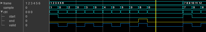
The input frame is ([1 2 3 4 5 6])', and the serializer is
configured to insert idle cycles around the valid samples:
One idle cycle between samples
Three idle cycles between frames
One value representing each sample (default output size)
You can specify these parameters by using either the Frame To
Samples block or the whdlFramesToSamples function.
The control signals start and end are 1 for the
first and last valid samples of the frame, respectively. The valid
signal is 1 for each valid input sample. The valid signal is 0 for
the idle cycles inserted between the samples and between the frames. The six-sample
frame is now represented by streaming data over 15 cycles.
Using the nextFrame Output Signal
The NR Polar Encoder, NR Polar Decoder, NR LDPC Encoder, NR LDPC Decoder, and RS Decoder blocks each provide an output signal to indicate when the block is ready to receive the start of a new frame. This signal is necessary because these blocks cannot accept a new frame at certain stages of internal computations, and the latency of those stages can vary with the values of input ports.
| Port | Description | Data Type |
|---|---|---|
| nextFrame | Boolean scalar that indicates when the block can accept the start of a new frame | Boolean |
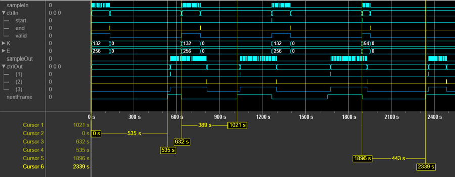
This waveform shows the NR Polar Encoder block processing several
frames. The nextFrame output signal is 0 when
the block is processing data, and 1 when the block is ready to
receive the start of a new frame. The cursors show the latency varying with the values
of the input K and E port values. For the
first frame with given K and E values, the
block must determine the message length and information bit mapping for those values.
This configuration stage means the block needs some time before it is ready to accept
the next input frame. For subsequent frames with the same values for
K and E, the block is ready sooner because
it does not need to recompute the configuration.
If the block receives an input start signal while
nextFrame is 0, the block discards the frame
in progress and begins processing the new data. This waveform shows an NR Polar
Encoder input frame (3) applied when nextFrame is
0. The block discards the frame in progress (2) and processes the
new frame (3) as normal.

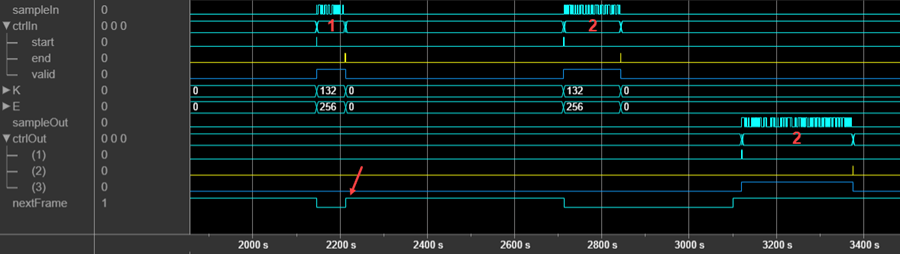
If the block receives an invalid input frame, for example, if the frame size is not
within the supported range, then the block sets nextFrame to
1 one cycle after the input end signal. This
behavior indicates that the input frame is discarded. This waveform shows an NR
Polar Encoder input frame (1) that does not have the correct number of
samples expected for the accompanying K and E
values. The waveform shows the nextFrame signal set to
1 immediately after the input end signal
from frame 1. The block discards the frame in progress (1) and processes the new frame
(2) as normal.