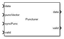
Main Content

Puncturer

Punctures data according to puncture vector

Since R2019b

  • Puncturer block

Libraries:
Wireless HDL Toolbox / Error Detection and Correction

Description

The Puncturer block punctures input data based on a specified puncture vector. The block accepts puncture vector either from the Input port or from the Property of the block and supports encoder rates from 1/2 to 1/7. It provides an architecture suitable for HDL code generation and hardware deployment.

The block supports Continuous and Frame mode operations and accepts both scalar and vector data. In Continuous mode, the block accepts input data and puncture vector, along with control signals valid and syncPunc and outputs punctured data with a valid signal. In Frame mode, the block accepts input data and puncture vector, along with a samplecontrol bus and outputs punctured data with a samplecontrol bus.

The block supports communication standards such as Wi-Fi (802.11a/b/g/n/ac), digital satellite communications, digital video broadcast (DVB), WiFi (IEEE 802.11a/b/g/n/ac), WiMax (IEEE 802.16), IEEE 802.16, HIPERLAN, and HiperMAN.

Ports

Input

expand all

Input data sample, specified as a scalar or vector.

If input is of vector type, the size of the input data must match with the selected Encoder rate parameter value.

For example, if the Encoder rate is 1/2, the input data size must be 2-by-1.

Data Types: Boolean | fixdt(0,1,0)

Control signal that indicates if the input data is valid. When this value is 1 (true), the block accepts the values on the data input port. When this value is 0 (false), the block ignores the values on the data input port.

Dependencies

To enable this port, set the Operation mode parameter to Continuous.

Data Types: Boolean

Puncture vector, specified as a column vector of binary values. The length of the puncture vector must be an integral multiple of n, where Encoder rate is 1/n. For encoder rates 1/2, 1/3, 1/5, and 1/6, the maximum length of the puncVector is 30 and for encoder rates 1/4 and 1/7, the maximum length of the puncVector is 28.

You can change the puncVector pattern, but its length must remain constant. If the maximum puncture vector length provided is 10, the block supports all the vector lengths below 10.

Example: For an encoder rate 1/2 and its puncture rates 2/3, 3/4, and 5/6, the respective vector lengths are 4, 6, and 10. To achieve these multiple rates, set the Puncture vector source parameter to Input port. To support the largest vector size, the vector length must be 10 for all rates. For 2/3 and 3/4 rates, pad the puncVector input with zeros to create a 10-element vector. The puncture vector for rate 3/4 is [1 1 0 1 1 0]'. For a vector length of 10, use [0 0 0 0 1 1 0 1 1 0]' as the input puncVector.

When the Operation mode parameter is set to Continuous, the block captures the value of puncVector when both syncPunc and input valid port signals are 1 (true).

When the Operation mode parameter is set to Frame, the block captures the value of puncVector when both ctrl.start and ctrl.valid signals are 1 (true).

Dependencies

To enable this port, set the Puncture vector source parameter to Input port.

Data Types: Boolean

Puncture synchronization signal, specified as a Boolean scalar value. This input is a control signal that synchronizes the puncture vector input with the input sample. When both syncPunc and valid are 1 (true), the block aligns the puncture vector to begin puncturing. The block captures the vector from either the puncVector input port or from the Puncture vector parameter.

The block ignores the puncVector signal values when syncPunc signal value is 0 (false).

Dependencies

To enable this port, set the Operation mode parameter to Continuous.

Data Types: Boolean

Control signals accompanying the sample stream, specified as a samplecontrol bus. The bus includes the start, end, and valid control signals, which indicate the boundaries of the frame and the validity of the input samples.

  • start — Indicates start of input frame.

  • end — Indicates end of input frame.

  • valid — Indicates that the data on the input data port is valid.

Dependencies

To enable this port, set the Operation mode parameter to Frame. In this mode, the block synchronizes the puncture vector using control signals in the input samplecontrol bus.

Data Types: bus

Output

expand all

Punctured output data, returned as an n-by-1 column vector, where n value ranges from 1 to 7.

Data Types: Boolean | fixdt(0,1,0)

Control signal that indicates when the sample from the data output port is valid. The block sets the valid port to 1 (true) when there is a valid sample on the output data port.

Dependencies

To enable this port, set the Operation mode parameter to Continuous.

Data Types: Boolean

Control signals accompanying the sample stream, returned as a samplecontrol bus. The bus includes the start, end, and valid control signals, which indicate the boundaries of the frame and the validity of the samples.

  • start — Indicates start of output frame.

  • end — Indicates end of output frame.

  • valid — Indicates that the data on the output data port is valid.

Dependencies

To enable this port, set the Operation mode parameter to Frame.

Data Types: bus

Parameters

expand all

Mode of operation, specified as one of these modes:

  • Continuous — Allows changes to puncVector at any time. To force the block to capture the new puncture vector, set the syncPunc parameter to 1 (true).

  • Frame — Allows changes to puncVector only at the start of a frame, indicated by ctrl.start.

Select the encoder rate for puncturing the data.

Source of puncture vector, specified as:

  • Input port — Specify the puncture vector using the puncVector port.

  • Property — Specify the puncture vector using the Puncture vector parameter.

The length of the puncture vector must be an integral multiple of n, where Encoder rate is 1/n. For encoder rates 1/2, 1/3, 1/5, and 1/6, the maximum length of the puncture vector is 30 and for encoder rates 1/4 and 1/7 the maximum length of the puncture vector is 28.

Dependencies

To enable this port, set the Puncture vector source parameter to Property.

Algorithms

expand all

The puncturing algorithm checks every n elements of a puncture vector, with an Encoder rate 1/n, until it reaches a nonzero combination. Then, it punctures the input data and provides the punctured output data.

For example, if the Encoder rate is 1/3 and the puncture vector is [0;0;0;1;0;1], the block checks every 3 elements until it reaches a nonzero combination in the puncture vector and then punctures the input data based on the type of inputs (scalar or vector) and operation modes (Continuous or Frame).

References

[1] Wireless LAN Medium Access Control (MAC) and Physical Layer (PHY) Specifications. IEEE Std 802.11™- 2016 Part 11.

[2] EN 300 421 V1.1.2 Digital Video Broadcasting (DVB); Framing structure, Channel coding and modulation for 11/12 GHz satellite services.

Extended Capabilities

Version History

Introduced in R2019b